Lightning Series Fiber Laser User Manual
10
Table 5 RS-232 Interface configuration parameters
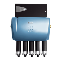
3) Control interface DB25 (CONTROL): It is used to connect the control wiring for remote
AD mode. The pin numbers are marked at the end of the control wiring, and the
definitions are shown in Table 6:
Figure 4 Control interface DB25
Table 6 DB25 Wiring Definition of Control Interface
When there is some fault, ports 7 and 20 will
be short-circuited. The maximum
short-circuit current here should not exceed
1A. Please add the series resistance according
to the actual operating condition; when the
laser works well, ports 7 and 20 will be
open-circuited.
External enable input
signal-
High level 18V-24V valid.
External enable input
signal+
External modulation
input signal-
Modulate output laser control, high level
18V-24V valid.
External modulation
input signal+