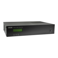
The EDC-2051 Conference Main Control Unit is a central component for managing conference systems, designed for quick installation and easy maintenance using CAT5E cables. It supports a variety of operational modes and offers extensive connectivity options for a comprehensive audio-visual setup.
Function Description:
The EDC-2051 serves as the core control unit for a conference system, facilitating communication and management of microphone units. It features a 4x20 digits LCD screen that displays crucial information such as conferencing modes, the ID of active microphones, and microphone volume levels. The unit supports multiple operating modes including Normal, Chairman, and Override, catering to different meeting dynamics.
For system integration, the EDC-2051 is equipped with an RS-232 interface, allowing connection to BXB HDS-720 IP Network AV Controllers, cameras, and other environmental control equipment. This enables a unified control environment for the entire conference setup. An XLR plug is also provided for connecting to external recording and audio equipment, ensuring high-quality audio capture and output.
The unit includes features for efficient microphone management, such as microphone auto-off settings (30/45 seconds) to conserve power and reduce ambient noise. It supports an open-mic mode or allows a maximum of 9 microphones to be activated simultaneously. A microphone auto-scanning function ensures the status of each connected microphone unit is checked before a meeting, preventing technical issues during a session.
The EDC-2051 is designed to work seamlessly with table-top chairman and delegate units (EDC-2011 and EDC-2012, respectively). These units offer high stability, allowing for parallel and series connections. Even if one unit is disconnected or out of order, others can continue to operate normally. Each chairman and delegate unit features a built-in 2.5” loudspeaker that automatically mutes when the speaking button is pressed, preventing sound feedback. A back-lighted indicator on the speaking button shows the speaking status, and the microphone capsule is equipped with an illuminating red ring for visual indication.
Chairman units are distinguished by a speaking priority button and have no quantity limitations, allowing for flexible positioning and sequencing. Both chairman and delegate units include built-in Ø3.5mm earphone and recording plugs with adjustable volume. The gooseneck microphones are designed with a shield and flexible tube for easy positioning without noise, available in standard lengths of 43/48/56/70cm. The design also incorporates features to prevent electromagnetic wave interference, ensuring clear audio.
Important Technical Specifications:
- Microphone Ports: 4 RJ45 ports at the back of the main control unit.
- Connectivity: Each RJ45 port supports a maximum of 15 units, with a total capacity of 50 units. With BXB extension power supply, it can connect up to 265 units.
- Display: 4x20 digits LCD screen.
- Control Interface: RS-232 for external control, UP/DOWN/MODE buttons on the front panel.
- Audio Output: XLR plug for recording and audio equipment, Aux Output (Unbalanced).
- Microphone Auto-Off: Settable to 30 or 45 seconds.
- Open-Mic Quantity: Adjustable from 1 to 9 microphones, or "ALL Mic".
- Operating Temperature: 0°C-40°C.
- Storage Temperature: -15°C-55°C.
- Relative Humidity: 45%-70% (non-condensing).
- Atmospheric Pressure: 86KPa-106KPa.
- Power Input: AC 90V-264V.
- DC Power Supply Fuse: DC 250V/8A.
- Operating Voltage: DC24V/6A (requires BXB's Extension Power Supply-EA11011M-240).
- Microphone Unit Connectivity: RJ45 ports x 2 for Cat5e cables (STP).
- Microphone Unit DIP Switch: 10-digit DIP switch for ID setting (binary combination). Chairman ID range: *01-*10. Delegate ID range: 001-255.
- RS-232 Protocol: Baud Rate 2400 bps N,8,1 (Hex). Commands for DELEGATE-MIC ON/OFF and CHAIRMAN-MIC ON/OFF with specific Byte1, Byte2, Byte3 (ID), and Byte4 values.
- Cable Length vs. Connected Units:
- 20M cable length: 50 units (total for 4 circuits)
- 40M cable length: 50 units (total for 4 circuits)
- 60M cable length: 50 units (total for 4 circuits)
- 80M cable length: 44 units (total for 4 circuits)
- 120M cable length: 36 units (total for 4 circuits)
- Maximum 15 microphone units per circuit within 100M. Beyond 120M, quantity decreases. An extension power supply (BXB's EPS-C083-C) is required for more than 15 units per single circuit.
Usage Features:
- Power On Sequence: Upon powering on, the unit displays firmware version, performs a memory check, and then a test link for connected microphones. The LCD then shows the main menu with current settings for operating microphone ID, meeting mode, open-mic quantity, and auto-off time.
- Microphone Connection Test: During power-on, a red LED indicator on microphone units will be constantly on for 5 seconds. If connection fails, the LED will flash. Re-powering the EDC-2051 after checking connections is recommended if issues arise.
- Front Panel LCD Navigation: The LCD displays various settings. Users can navigate and adjust parameters using the MODE, UP, and DOWN buttons.
- NO (Operating Mic ID): Displays IDs of active microphones (up to 3 per page). Chairman MICs are *01-*10, Delegate MICs are 001-255. If more than 3 microphones are active, "← →" icon appears, and users can scroll through IDs.
- MODE (Meeting Mode): Selectable modes include Normal (delegates speak freely within open-mic limit), Chairman (only chairman can speak), and Override (delegates take turns, new speaker overrides the oldest active delegate, chairman always unrestricted).
- OPEN-MIC (Open-Mic Quantity): Sets the number of simultaneous speaking microphones (1-9 or ALL Mic).
- AUTO-OFF (Automatic Mic-off): Configures microphones to turn off automatically after 30 or 45 seconds of no sound, or sets to "Invalid" for manual turn-off.
- SYSTEM LEVEL (Volume Adjustment): Adjusts the system volume (default 80%, 0% is mute) in increments of +2 or -2. This also affects the built-in loudspeaker volume of microphone units and earphone/recording output.
- SPK SETTING (Microphone Speaker Setting): Turns the built-in loudspeaker of microphone units ON (default) or OFF. Earphone and recording outputs still function normally when SPK is OFF.
- Automatic Saving: Settings are automatically saved after 30 seconds of inactivity, and the system returns to the default page. No manual save button is required.
- Microphone Unit Features:
- Gooseneck MIC plug (DIN TYPE).
- Control button with indicator light.
- Earphone volume control.
- Recording plug (Φ 3.5 stereo).
- Loop connector (CAT5E).
- DIP switch for MIC ID setting (located at the bottom of the unit).
- Microphone Placement: EDC microphone units are cardioid type, optimized for in-front speaker voice reception. Proper distance between speaker and microphone is crucial to avoid sound offset.
Maintenance Features:
- Safety Instructions: Emphasizes reading the manual, following warnings, using BXB-recommended accessories, ensuring proper power cord fixation, avoiding liquid spills, and contacting technicians for issues like damaged cords, liquid ingress, abnormal operation, physical damage, or incomplete function.
- Grounding: All cables must be bonded to the same grounding point to reduce lightning damage risk.
- Installation: Install carefully, avoiding impacts and fierce shaking.
- Disassembly: Do not disassemble or remodel the unit due to high voltage and sensitive circuits. Servicing should be performed by qualified technicians.
- Temperature and Environment: Avoid improper temperature, moisture, and power levels. Ensure adequate coverage if used outdoors.
- Cleaning: Do not use chemical or liquid detergents. Use a damp cloth for cleaning.
- Power Cycling: Avoid rapid power on/off cycles to maintain regular operation of sensitive electronic circuits.
- ESD Safety: Static electricity treatment of printed circuit boards should follow ESD safety measures, and ground connection must be well done.
- Voltage Accordance: Be aware of the voltage accordance with the country's standards.
- Qualified Technicians: Only qualified technicians should disassemble the unit cover. Power must be unplugged before disassembly and re-plugged only after the cover is back in place.
- DIP Switch Adjustment: All adjustments to the microphone unit DIP switches for ID setting should be done after the system has been shut down.
- RJ45 Port Warning: The RJ45 microphone unit ports are not standard LAN ports. Plugging in other equipment can damage the unit.