INSTALLATION & MAINTENANCE MANUAL • Approved Document No. DFU7004010 Rev 3 • Page 11 of 24
LPCB APPROVED CFP 2/4/8 ZONE FIRE ALARM PANEL
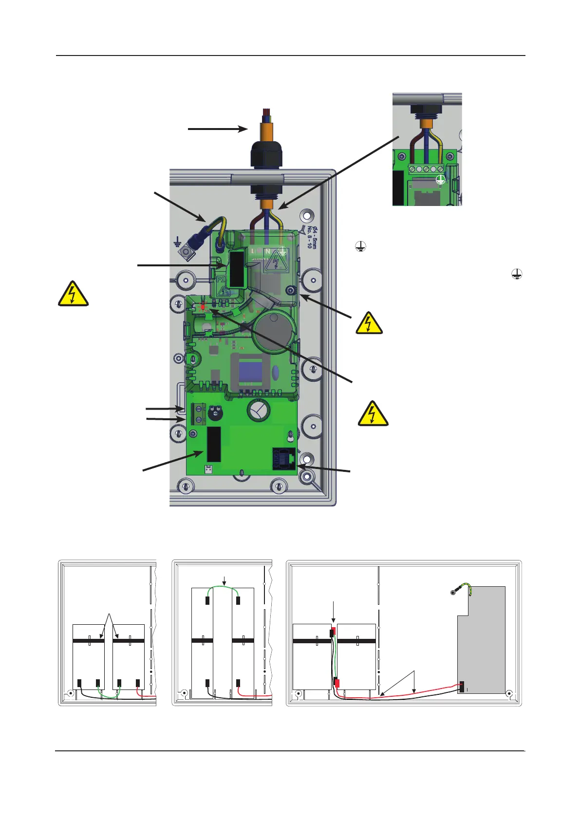
Figure 9 : Battery location and connection details
+–+–
+
I
+
+
I
–
+
–
Location of small
sized batteries
typically 1.2 Ah
Location of medium
sized batteries
typically 2.1 Ah
+
+
–
–
+
Take care to arrange
batteries so terminals
do not touch
Location of large
sized batteries
typically 3.0 Ah
Connection of leads
to Power Supply PCB
Run the battery leads
(supplied) through slits
in the plastic ribs
R E D
BLACK
Nylon
tie wraps
Link wire
Figure 3 : Power Supply PCB layout and Mains connection (Full Protective Cover & Cable Cover shown fitted)
CONN2
BLK-
RED+
VR1
F2
F1.6A
PL2
PL1
THIS
WAY UP
Incoming Mains Cable
This cable MUST be segregated from
other cables. Good quality cable
glands MUST always be fitted.
Mains Fuse (F1)
Exposed Live
parts under fuse
cover. Isolate
before removal.
Battery Connector
(CONN2)
(Leads supplied in
the panel’s accessory
pack.) See below for
connection details.
Mains Input (CONN1)
L = Live (BROWN)
N = Neutral (BLUE)
= Earth (GREEN/YELLOW)
The incoming Mains earth wire MUST
be connected to the terminal marked
and NOT to the base earth distribution
post.
CONN1
NL
Cable cover
removed
PSU Earth Distribution Strap
DO NOT operate the panel
without first connecting
this strap to the base
earth distribution post.
Battery Fuse (F2)
Connector Cable Socket (PL1)
Connect other end of lead to
the rear of Main Control PCB.
Hazardous Voltages Present LED
When lit red, hazardous
voltages are present under the
two covers. Allow to discharge
for at least 5 minutes before
removal & handling.
Exposed live parts under cable
cover. Isolate first, then remove
the small cable cover by loosening
its single retaining screw which is
retained in the cover. Only operate the
PSU with this cover securely fitted.