FIRST FIX
All system wiring should be installed to meet BS 5839 Part 1 and BS 7671 (Wiring Regulations).
Other national standards of installation should be used where applicable.
Cable types and limitations
Consult Clause 26 of BS 5839 Part 1: Fire detection and fire alarm systems for buildings - code of practice
for system design, installation, commissioning and maintenance, for detailed information on cables,
wiring and other interconnections.
To comply with EMC (Electro Magnetic Compatibility) regulations and to reduce the risk of electrical
interference in the system wiring, we recommend the use of fire-resistant screened cables throughout
the installation. Cables such as FP 200, Firetuff™, Firecel™ and MICC may be acceptable provided they are
properly terminated at the fire panel and meet national standards/the system specification as applicable.
Correct cable glanding is essential and due regard should be made to any system specifications which
demand a certain cable type.
Mains wiring
All wiring should be installed in accordance with the current edition of the IEE Wiring Regs. (BS 7671), or
relevant local & national standards. The requirement for the Mains supply to the panel is fixed wiring (no
less than 1mm
2
and no greater than 2.5mm
2
), either using 3-core cable, or a suitable three conductor system
fed from an isolating switched fused spur at 3 A, or a 6 A Type B circuit breaker to IEC/EN 60898-1.
The Mains supply MUST be exclusive to the panel and be reliably earthed at the indicated earthing post.
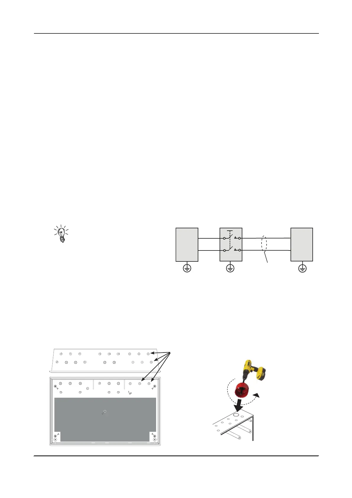
Hint! As an alternative to
a switched fused spur, a
double-pole isolating switch
(S), with 3mm air gaps on the
contacts & switching L & N only, may be used
in the Mains feed from the Main Distribution
Board (A) to the Panel (C), providing it meets
the appropriate wiring regulations (see
drawing right).
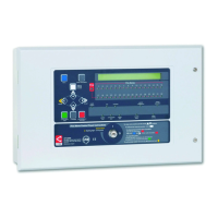
Do not drill any additional holes
for cable entry in this shaded area.
This is where the PCBs and
backup batteries will be located.
INSTALLATION & MAINTENANCE MANUAL • Approved Document No. DFU7004010 Rev 3 • Page 6 of 24
LPCB APPROVED CFP 2/4/8 ZONE FIRE ALARM PANEL
Planning the cable layout in the panel
The detector and sounder circuit cabling is classed as extra low voltage and should be segregated away
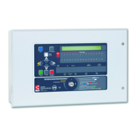
from Mains voltages. Careful planning is needed to ensure this, see figure 2 (below) for guidance. Drill
centre points are provided in the panel base to aid drilling tools. Cut out suitable holes in the panel using
a hole saw directed by a pilot bit in the centre of the hole saw. Always ensure that if a hole is cut out it is
filled with a good quality strain relief, cable gland. Any unused holes must be securely blanked off.
Figure 2 : Location of centre points for hole removal
A
S
C
≥ 1.0 mm
2
< 2.5 mm
2
These four drill centre
points are for incoming
Mains cable only
Holes should be cut
out using a hole saw
with a pilot bit.