CONTENTS
EN54 Compliance Statement .............................................................................................................. 3
Basic Overview & Key Features ......................................................................................................... 3
Important Notes .................................................................................................................................. 4
The Fire Panel Enclosure .................................................................................................................... 5
First Fix .......... .......................................................................................................................................6
Cable types and limitations ............................................................................................................................. 6
Mains wiring ..................................................................................................................................................... 6
Planning the cable layout in the panel .......................................................................................................... 6
Fixing the base onto a wall ............................................................................................................................ 7
Typical detector circuit wiring ....................................................................................................................... 7
Typical sounder circuit wiring ......................................................................................................................... 8
Typical auxiliary input wiring ......................................................................................................................... 8
Typical auxiliary output wiring ...................................................................................................................... 9
Second Fix ......................................................................................................................................... 10
Connecting the panel .................................................................................................................................... 10
Installing the Power Supply PCB ................................................................................................................... 10
Connecting the Mains .................................................................................................................................... 10
Connecting the standby batteries ................................................................................................................ 10
Installing the Main Control PCB .................................................................................................................... 12
Connecting the detector and sounder circuits ............................................................................................ 13
Connecting the auxiliary inputs, auxiliary outputs and relay outputs ....................................................... 13
Programming the Panel ................................................................................................................... 14
An overview of the panel’s controls ............................................................................................................ 14
Engineer functions ......................................................................................................................................... 14
Accessing the engineer controls ................................................................................................................... 16
Programming coincidence, non-latching zones, delays, zones into test, sounder functions ................. 16-17
Fault Diagnosis ................................................................................................................................. 18
Fault indications ............................................................................................................................................ 18
Zone faults ...................................................................................................................................................... 19
Power supply faults ........................................................................................................................................ 19
System faults .................................................................................................................................................. 21
Repeater faults ............................................................................................................................................... 22
Sounder faults ................................................................................................................................................ 22
Remote output faults .................................................................................................................................... 22
Maintenance ..................................................................................................................................... 22
Standby Battery Calculation Guide .................................................................................................. 23
Technical Specification ...................................................................................................................... 24
INSTALLATION & MAINTENANCE MANUAL • Approved Document No. DFU7004010 Rev 3 • Page 2 of 24
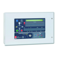
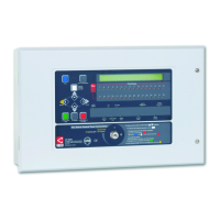
LPCB APPROVED CFP 2/4/8 ZONE FIRE ALARM PANEL
Errors & Omissions Excepted. The manufacturer of this product operates a policy of continuous improvement and reserves the right to alter product
specifications at its discretion and without prior notice. All of the instructions covered in this manual have been carefully checked prior to publication.
However, no responsibility can be accepted by the manufacturer for any inaccuracies or for any misinterpretation of an instruction or guidance note.
Manufacturer: Computionics Limited (C-TEC), Challenge Way, Martland Park, Wigan, Lancashire WN5 0LD. www.c-tec.com
Niederlassung Deutschland: C-TEC Germany Limited, Virchowstr. 32, D-33332 Gϋtersloh. www.c-tec-germany.de