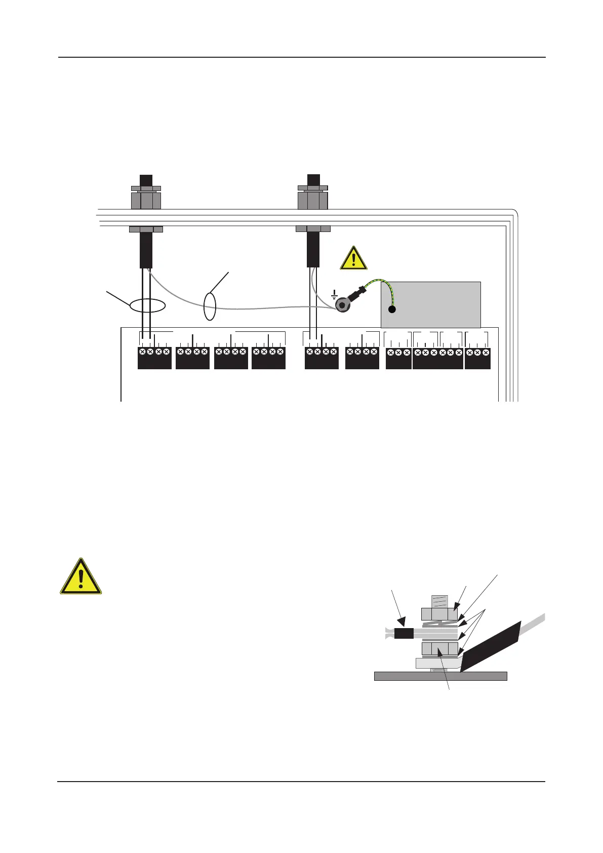
Connecting the detector and sounder circuits
Incoming detector circuits and conventional sounder circuits (if used) should be connected to the relevant
connector block on the Main Control PCB as shown in figure 11 below.
For typical detector circuit and conventional sounder circuit wiring diagrams, please refer to pages 7 and 8.
Figure 11 : Detector circuit and conventional sounder circuit connections
Connecting the auxiliary inputs, auxiliary outputs and relay outputs
Incoming auxiliary inputs, auxiliary outputs and relay outputs cables should be connected to the relevant connector
block terminals on the Main Control PCB. If screened cables have been used, all screens should be adequately
insulated and connected between the nut and washers on the base earth distribution post (see below) using eyed
crimp connectors (as per the detector and sounder circuit examples shown in figure 11).
For a full description of the inputs and outputs available on the panel, including typical wiring diagrams, please
refer to pages 8 & 9.
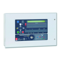
Important notes regarding the earthing of screens
All screens should be adequately insulated and
connected between the nut and washers on the
base earth distribution post (see right) using suitable
eyed crimp connectors. Do not disturb the lower nut,
this must be secure to ensure earth continuity. The base earth
distribution post is provided for terminating earth screens or
drains and not as the main earthing point. The system designer
or installer must review the external earth bonding (if required)
with respect to the national wiring rules. That is, if the type of
installation requires protective earth bonding, then this must be
applied externally and in conjunction with the type of earthing
system employed on that particular site. This must always be
done with regard to the appropriate national wiring rules.
LPCB APPROVED CFP 2/4/8 ZONE FIRE ALARM PANEL
INSTALLATION & MAINTENANCE MANUAL • Approved Document No. DFU7004010 Rev 3 • Page 13 of 24
Z1 Z2 Z3 Z4 Z5 Z6 Z7 Z8 SC1SC2 SC3SC4
SOUNDER CIRCUITSDETECTOR CIRCUITS
CONN5
CONN6
CONN7
–
+
–
+
–
+
–
+
–
+
–
+
–
+
–
+
–
+
–
+
–
+
–
+
insulated
screens
insulated
conductors
See ‘Important notes
regarding the earthing
of screens’ section below
CC
STUPNI
OUTPUTS
AUX
AUX
24V
0V
ALT
RST
CONN8
CONN9
REM
FAULT
NO
NC
C
NO
NC
C
CONN10
CONN2
nut
plain
washers
crimped
connections
Do not untighten lower nut
spring
washer
screens