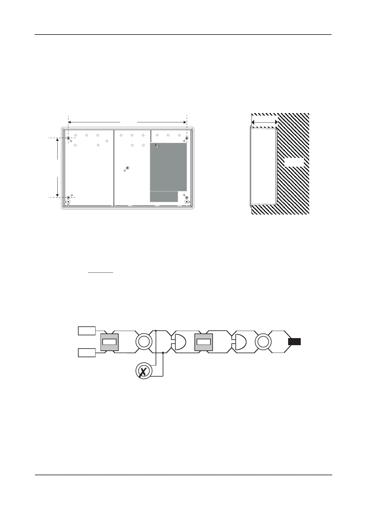
Fixing the base onto a wall
Using the five mounting holes provided (see figure 3 below), fix the base securely onto a vertical wall, ≤2 m
mounting height. The mounting holes are suitable for use with No.8-10, or 4-5mm countersunk screws.
Assess the condition and construction of the wall and use suitable screw fixings for the in-service weight of
the product.
Any dust or swarf created during the fixing process must be kept out of the fire alarm panel and care must
be taken not to damage any wiring or components.
Figure 3 : Internal view of the back box with PCBs removed / side view for flush mounting
INSTALLATION & MAINTENANCE MANUAL • Approved Document No. DFU7004010 Rev 3 • Page 7 of 24
LPCB APPROVED CFP 2/4/8 ZONE FIRE ALARM PANEL
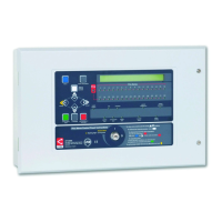
Typical detector circuit wiring
Depending on the model purchased, two, four, or eight detector circuit connections are available on the
fire alarm panel.
Refer to the specification on page 24 for the maximum number of devices that may be fitted to each
circuit. Note: The number of devices affects the standby time of the system, and this should be taken into
consideration when selecting the standby batteries. See page 23 for more information.
Figure 4 : Typical detector circuit wiring
Connect an end-of-line (EOL) capacitor (provided in the panel’s accessory pack) across the terminals of the
last device on each circuit to allow the wiring to be monitored.
Detector bases with integral continuity diodes must be used to ensure manual call points remain operational
when a detector head is removed from its base.
Manual call points with integral resistors must be used to prevent a short circuit fault occurring instead of
a fire condition when activated.
For more specific device wiring information, please refer to the manufacturers’ own instructions.
The wiring for each detector circuit should be connected to the relevant 5mm connector block on the
Main Control PCB and their screens terminated at the panel’s base earth distribution post (see page 13 for
detailed second fix connection information).
SMOKE
OR HEAT
DETECTOR
MANUAL
CALL
POINT
MANUAL
CALL
POINT
SMOKE
OR HEAT
DETECTOR
END OF LINE
CAPACITOR
+
PANEL
DETECTOR
CIRCUIT
TERMINALS
–
✗
DO NOT SPUR
(wiring not
monitored)
75mm
WALL
339mm
170mm
Ensure no
fixing devices
are located
underneath the
Power Supply
PCB to avoid
compromising
electrical
safety
Fixing centres
Fixing centres