Typical auxiliary output wiring
Two auxiliary open collector outputs and one auxiliary output connections are available on the panel, as detailed below:
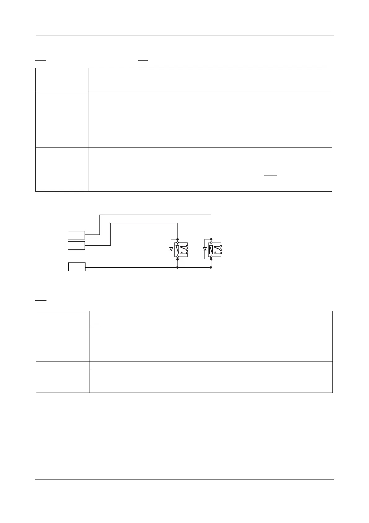
Figure 7 : Typical auxiliary output wiring for open collector outputs
Two relay outputs are available on the panel, as detailed below:
Connect each output to the relevant 5mm connector block on the Main Control PCB and terminate their screens
at the panel’s base earth distribution post (see page 13 for more details).
LPCB APPROVED CFP 2/4/8 ZONE FIRE ALARM PANEL
INSTALLATION & MAINTENANCE MANUAL • Approved Document No. DFU7004010 Rev 3 • Page 9 of 24
REM
RESET
AUX 24V
+
–
+
–
REMOTE
OUTPUT
RELAY
RESET
RELAY
To protect the output stage, only
24V polarised relays with back EMF
diodes should be used. If any of
the relays are to be used to switch
Mains potentials, then suitable
relays should be chosen and
installed and wired accordingly, so
as not to compromise the electrical
safety of the fire alarm system.
Auxiliary Fire
Output
(AUX)
Turns on during any fire alarm condition and off when the panel is reset. This output does
not turn on if the Class Change or Alert inputs are asserted, or if the panel’s Silence/Resound
Sounders button is pressed to manually evacuate the building (unless there are other fire
alarm conditions present on the system). Note: It is possible to delay the activation of the
Auxiliary Output to correspond with any zone delay(s) that have been programmed into
the panel at Access Level 3. If required, the Auxiliary Output can be disabled by the user.
This output will not operate from a non-latching zone.
Fault Output
(FAULT)
This output is normally energised. When a fault occurs, the output turns off to ensure
failsafe operation even in the event of total power loss. It is important that the peripheral
part of the system this output drives is able to handle the output’s ‘normally on’ condition.
If required, this output can be disabled by the user.
Reset Output
(RESET)
Turns on during the panel’s reset cycle. Can be used for resetting fire alarm system devices
such as roller-shutter doors or beam detectors. This output remains active for approximately
one second after all other outputs have returned to normal.
Remote Output
(REM)
Turns on during any new fire alarm condition or when the panel’s Silence/Resound Sounders
button is pressed to manually evacuate the building. The output turns off when the panel is
silenced. This output does not turn on when the Class Change or Alert inputs are asserted
(unless there are other fire alarm conditions present on the system). Note: It is possible to
delay the activation of the Remote Output to correspond with any zone delay(s) that have
been programmed into the panel at Access Level 3. If required, the remote output can be
disabled by the user. When the Remote output is activated the Remote Output light will be
lit. This output will not operate from a non-latching zone.
Auxiliary 24V
Output
(AUX 24V)
This output provides a positive voltage supply for peripheral loads (such as relays) which are
controlled from the above outputs. It is protected by a current limiting fuse which trips if
one or more of the loads are shorted. This affects all loads and results in appropriate faults
being reported at the panel. The current consumed by this output must be considered when
calculating battery standby times. DO NOT CONNECT DOOR HOLDER CIRCUITS TO THIS
OUTPUT AS THEY WILL REDUCE BATTERY STANDBY TIME - USE A SEPARATE POWER SUPPLY.