Series 90 Setup Manual Page 55
APPENDIX A - SCANNER RESISTOR BANK
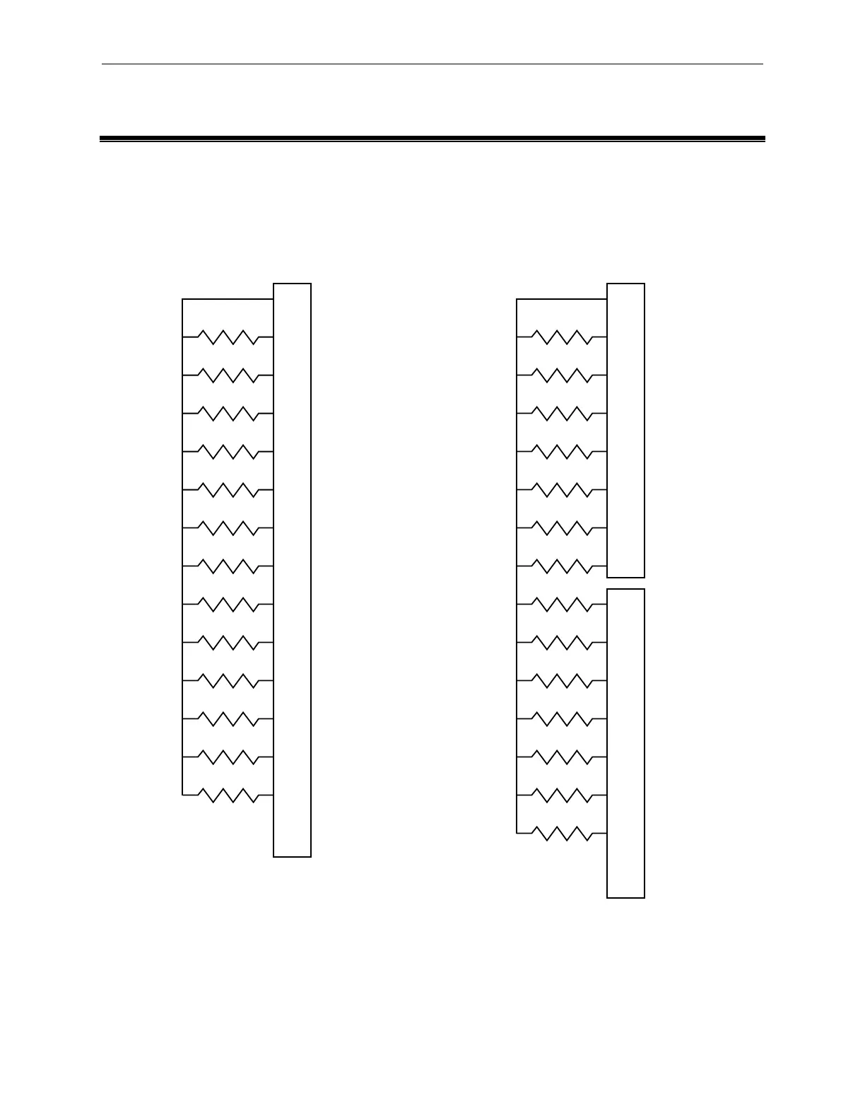
A bank of resistors is used to test the scanner board and scanner control board. The resistors can
be soldered directly to a mating connector, or optional calibration boards may be used. The low-
voltage testers use thirteen resistors and the high-voltage testers use fourteen. The values and
corresponding connector locations are shown below.
R1 - 3.32Ω
R2 - 39.2Ω
R3 - 82.5Ω
R4 - 392Ω
R5 - 1kΩ
R6 - 3.92kΩ
R7 - 12.1kΩ
R8 - 43.2kΩ
R9 - 121kΩ
R10 - 267kΩ
R11 - 475kΩ
R12 - 825kΩ
R13 - 3.32MΩ
1
5
9
13
17
21
25
29
33
37
41
45
49
53
64
R1 - 3.32Ω
R2 - 39.2Ω
R3 - 82.5Ω
R4 - 392Ω
R5 - 1kΩ
R6 - 3.92kΩ
R7 - 12.1kΩ
R8 - 43.2kΩ
R9 - 121kΩ
R10 - 267kΩ
R11 - 475kΩ
R12 - 825kΩ
R13 - 3.32MΩ
R14 - 100MΩ
1
5
9
13
17
21
25
29
1
5
9
13
17
21
25
32
J1
J2
Low-voltage Resistor Bank High -voltage Resistor Bank
Note:
The 100 M
resistor, R14, must be rated at 1500 vdc or higher.



 To Next Page