2012 Portable Spa
LTR20121001, Rev. A
Preparing for Your New Portable Spa
www. c a l s p a s. c o m
7
OPYRIGHT 2007
MADE IN U.S.A
To an optional
fuse-protected
expansion board
DIP Switch A10 must be OFF.
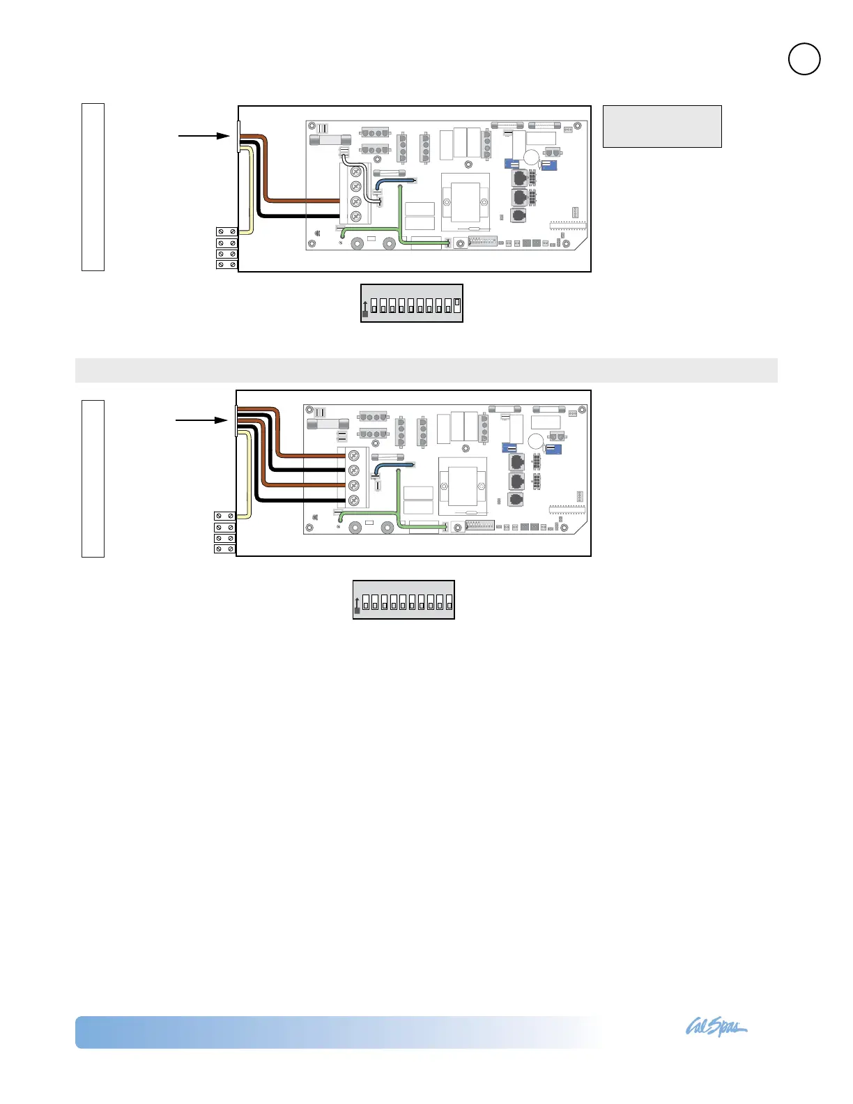
Three Phase Service
GREEN/
YELLOW
(Ground)
BROWN (Hot)
BROWN (Hot)
BLUE (Neutral)
BROWN (Hot)
From RCD Box
GROUND TERMINAL BLOCK
(ATTACHED TO OUTSIDE
OF SYSTEM BOX)
O
N
SWITCHBANK
1
2
3 4
5 6
7
8 9
10
For 1 x 16 Amp Service:
DIP Switch A10 must be ON.
For 1 x 32 Amp Service:
Set DIP Switch A10 such that total system amperage
draw never exceeds rated service input.
Completely remove the white
wire from J26 and J32, or J25.
Completely remove the blue wire
from J28 and J59.
3 x 16 Amp
5 Wires (3 Lines + 1 Neutrals + 1 Protective Earth)
Protective Earth wire (Green / Yellow) must be
connected to system ground terminal as marked.
IMPORTANT: Service MUST include a neutral wire
with a line to neutral voltage of 230VAC.
If an expansion board is installed,
black wire must connect to J28
(Line 2) only.
DIP Switch A10 must be OFF.
Dual Service
GREEN/
YELLOW
(Ground)
BLUE (Neutral)
BROWN (Hot)
BLUE (Neutral)
BROWN (Hot)
From RCD Box
O
N
SWITCHBANK
1 2 3 4 5 6 7 8 9 10
GROUND TERMINAL BLOCK
(ATTACHED TO OUTSIDE
OF SYSTEM BOX)
2 x 16 Amp
5 Wires (2 Lines + 2 Neutrals + 1 Protective Earth)
Protective Earth wire (Green / Yellow) must be
connected to system ground terminal as marked.
Completely remove the white
wire from J26 and J32.
Note: J32 and J25 are
electrically identical. The white
wire may be attached to either
terminal before removal.
Single Service
GREEN/
YELLOW
(Ground)
BLUE (Neutral)
BROWN (Hot)
From RCD Box
O
N
SWITCHBANK
1 2 3 4 5 6 7 8 9 10
19
GROUND TERMINAL BLOCK
(ATTACHED TO OUTSIDE
OF SYSTEM BOX)
is is the factory
default configuration.
1 x 16 Amp or 1 x 32 Amp
3 Wires (1 Line + 1 Neutral + 1 Protective Earth)
Protective Earth wire (Green / Yellow) must be
connected to system ground terminal as marked.
6115 and 6215 Circuit Board Connection





 To Next Page