Page 13
2.3 ELECTRICAL INSTALLATION
ELECTRICAL SAFETY
It is important to ensure that all aspects of the installation comply with the latest I.E.E. Regulations.
It is also important to ensure that any remote devices which terminate within the pool hall are of the type and
voltage as specified in the latest I.E.E. Regulations.
The machine should be installed in accordance with EMC2004/108/EC.
PROTECTED SUPPLY
Whilst not mandatory, Calorex recommend that an R.C.C.B. is always fitted or that the supply is to local
electricity authority recommendations, and that all ducting is bonded in accordance with these regulations.
The supply to the machine should incorporate fuses or motor rated circuit breakers (type GU) to specified rating
(see data sheet) H.R.C. fuses are recommended. An all pole swtched isolator must be fitted within clear view of
the machine and not more than 2 metres away. The isolator must have a minimum of 3mm air gap when in the off
position.
INCONSISTENT ELECTRICAL SUPPLY.
The following limits of operation must not be exceeded if Calorex machines are to be guaranteed either in
performance or warranty terms :-
Voltage single phase - 207V min, 253V max
Frequency - 47.5Hz min, 52.5Hz max.
N.B The voltage must be measured at the heat pump mains terminals with all the fans/compressors
running at the rated condition.
CORRECT CABLE SIZING
The cable supplying electricity to a machine with a given load must increase in cross sectional area (CSA)
as the length increases in order that the voltage drop within the cable does not exceed recommended limits.
Cable sizing should be calculated by an approved electrician with due consideration to I.E.E. and local
codes of practice.
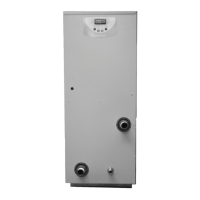
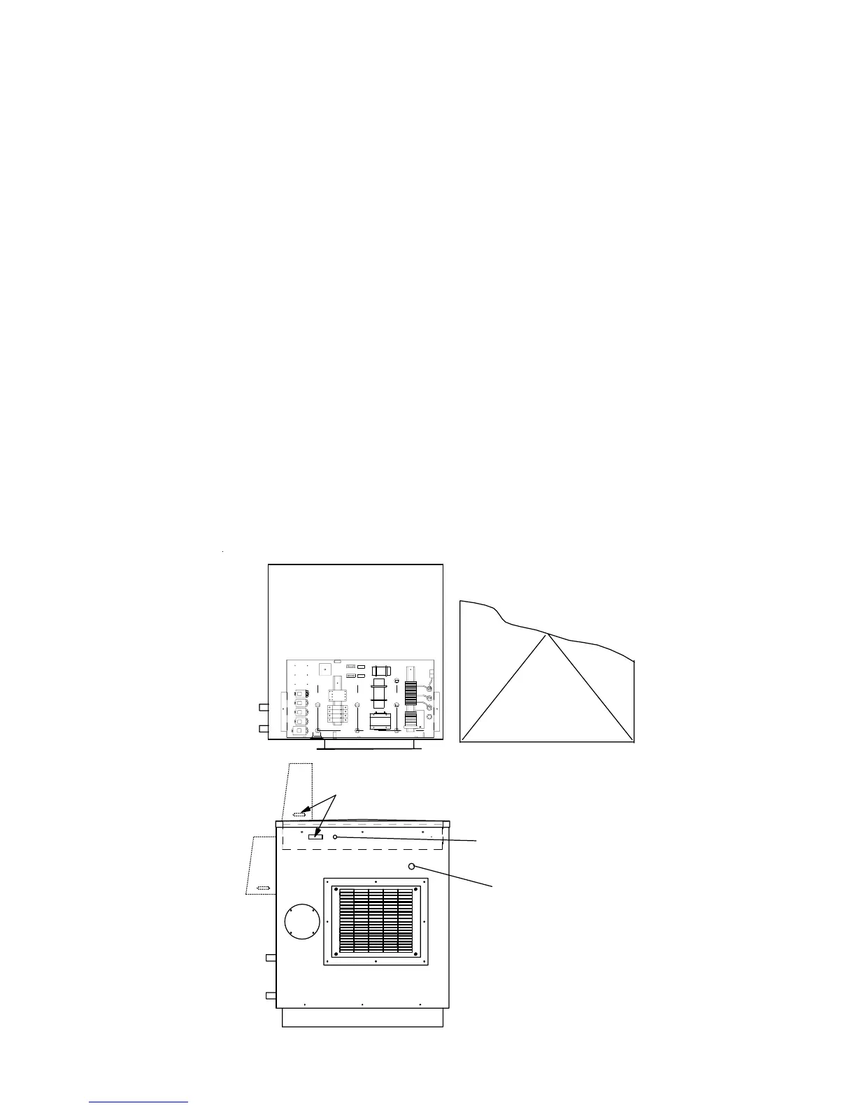
MAINS ENTRY
POINT
ELECTRIC BOX LIVE
INDICATOR LAMP
CONTROL CONSOLE
CONNECTION POINT
REMOVE LID TO GAIN
ACCESS TO ELECTRIC BOX
ELECTRIC BOX
REMOTE
OVERRIDE
SWITCH
REMOTE
ON/OFF
(12V)
N L
BOILER
DEMAND
REM OTE
POWE R
INDICATER
(12V)
F1 2.5A
F2 1.0A
COMP
FAN H
FAN L
CON T
A1
A2
12
3
4
56
21 22
COMP
CONT
RE1
R1 R2 R3 R4
4 5 6 7 8 9 1011 12
13
141516171819202122232425262728293031