Page 33
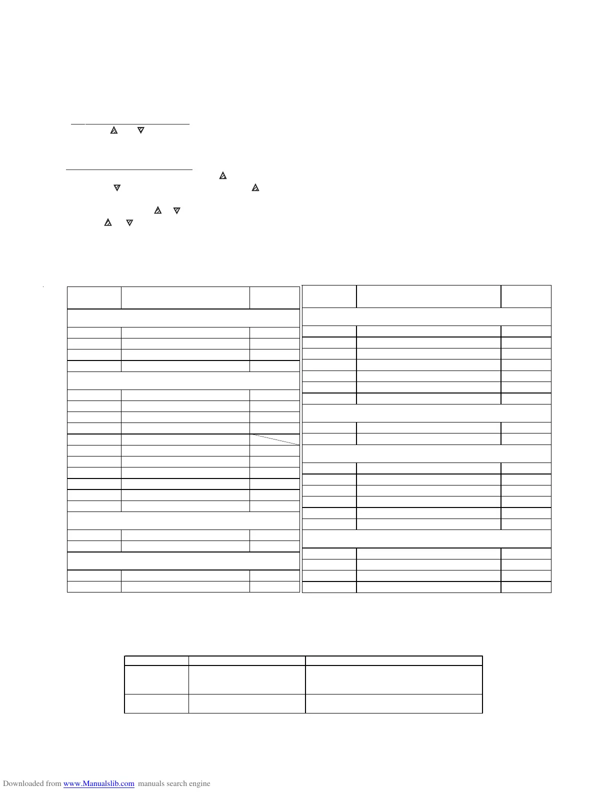
DISPLAY ERROR ACTION
E1 OR -E1
PROBE INTERRUPTED OR
SHORT CIRCUIT
VERIFY CORRECT CONNECTION BETWEEN
PROBE AND STAT, THEN VERIFY CORRECT
FUNCTIONING OF PROBE.
EEPr INTERNAL MEMORY ERROR
CHECK AND, IF NECESSARY REPROGRAMME
THE PARAMETERS FUNCTION
THERMOSTAT CONTROL
PARAMETER SETTING INSTRUCTIONS AA300AVH(F) HUMIDITY
The digital display may show the following codes, these are errors. Check the table below.
PARAMETER FUNCTION SETTING
NAME
GROUP כSP (RELATIVE TO SET POINT )
nS P FA CTOR Y S ETTING 1
SP1 SET POINT 1 60
SPLL LOW SET POINT 15
SPHL HIGH SET POINT 80
GROUP כInP (RELATIVE TO THE MEASURED OUTPUT )
SEnS PROBE TYPE 0.10
**** SSC LOW SCALE LIMIT 0
**** FSC HIGH SCALE LIMIT 100
dP NO OF DECIMAL FIGURES 0
**** Unit TEMP UNITS
FiL INPUT DIGITAL FILTER OFF
Fild FACTORY SET PASSWORD OFF
OFSt MEASURING OFFSET 0
rot ROT OF MEASURING STRAIGHT LINE 1.000
InE OPE FUNC IN CASE OF ERROR Our
OPE OUTPUT PWR IN CASE OF ERROR 0
GROUP כOut (RELATIVE TO OUTPUTS)
01F FUNCTIONING OF OP1 1.rEG
02F FUNCTIONING OF OP2 Alno
GROUP כAL1 (RELATIVE TO ALARM AL1)
0AL1 OUTPUT, ALARM AL1 ADDRESSED Out2
AL1t ALARM AL1 TYPE HidE
PARAMETER FUNCTION SETTING
NAME
GROUP כAL1 (RELATIVE TO ALARM AL1) cont
Ab1 ALARM AL1 FUNCTIONING 0
AL1 ALARM AL1 THRESHOLD 5
AL1L LOW THRESHOLD BAND ALARM AL1 -1999
AL1H HIGH THRESHOLD BAND ALARM AL1 9999
HAL1 ALARM AL1 HYSTERESIS 3
AL1d ACTIVATION DELAY OF ALARM AL1 OFF
AL1i ALARM AL1 WHEN MEAS ERROR no
GROUP כLBA (RELATIVE TO LOOP BREAK ALARM )
OLbA ALARM TYPE/SECOND OUTPUT OFF
LbAt HEAT/COOL CONTROL OUTPUT 1 OFF
GROUP כ rEG (RELATIVE TO CONTROL )
Cont CONTROL TYPE On.FA
Func FUNCT. MODE OUTPUT 1rEg CooL
HSEt HYSTERESIS OF ON/OFF CONTROL 3
Slor GRADIENT OF RAMP RISE 1nF
dur.t DURATION TIME 1nF
SLoF GRADIENT OF RAMP FALL 1nF
GROUP כPAn (RELATIVE TO USER INTERFACE)
USRB FUNCTION OF KEY 'U' noF
diSP VAR VISUALISED ON DISPLAY dEF
AdE SHIFT INDEXING FUNCTION OFF
Edit FST PROG ACTIVE SET POINT & ALARMS SAE
SETTING INSTRUCTIONS (THERMOSTATS MARKED TLK38)
NOTE : These parameter settings are programmed by the supplier to the figures shown below and
should not need altering.
1. To Program the Set Point. Press down P: SP (Set Point) and current set point value will be displayed alternately.
Press the or key to change the value of SP. Once the desired value is displayed press P to memorise the
value. The display will revert to the present reading.
NOTE : If anything else shows on the display leave alone for 1 minute, until the display returns to normal.
2. To Program the Parameters. Press and hold down the P key for approximately 2 seconds. You will then enter the
Programme Control Menu. Press the key to reach ConF then press P again and enter the Password -281 by
holding the key. If you pass -281 press the key to go back, then press P again, this will take you into the
Programmable Menu. To read or change the setting press P, then to change the setting
(if needed) press the or key . Once the correct setting is reached press P again. To move to the next setting
press the or key and repeat above.
*** Note some functions are not present either because they are instrument dependent or because they are disabled.
To return to Programmable Group Menu leave keys alone for approximately 20 seconds.
To return to Normal Mode leave alone for approximately 20 seconds.