Chapter 2: System hardware 90
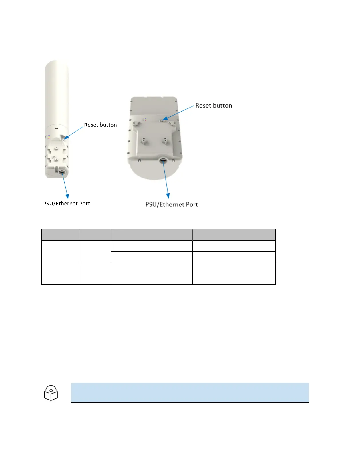
Figure 27 :
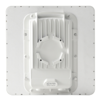
PMP 450 MicroPoP (Omni and Sector) Series - ODU rear interfaces
Table 61 :PMP 450 MicroPoP Series – ODU rear interfaces
Port name Connector Interface Description
Main PSU RJ45 PoE input Power over Ethernet (PoE).
10/100/1000BASE-T Ethernet Data
Reset button - Push button Short press: Reboot the device
Long press: Recovery mode
MicroPoP Lightning Arrester details
By lowering the omni (mast O.D. 2.125 inches) on the mast such that the mast is 0.5m higher than the
product will work for lightning protection but hurts the omni pattern as shown Figure 1 in orange trace.
The 2.125” mast is at 270 degrees and you are looking top down onto the mast. The orange pattern has
major ripple due to the mast being beside the omni antenna and causing reflections. If the lightning rod
diameter is smaller such as 0.3 to 0.625 (5/8) inches maximum, then the omni pattern is not effected
(ripple is no worse than the base line plastic mast), that is the light blue and blue traces shown below,
horizontal polarity pattern is to the left, taken at 5.850 GHz. 5.15 and 5.55 GHz were measured and had
very similar results as at 5.85 GHz.
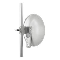
The below Figure 28 andFigure 29 shows the desired implementation, using a 4-foot minimum lighting rod
opposite of the omni radio.
Note
The 2.125 inch pipe does not extend any more than three inches above the omni mast bracket.
 Loading...