2
This document contains proprietary information protected by copyright. All rights
are reserved. No part of this manual may be reproduced by any mechanical,
electronic or other means, in any form, without prior written permission of the
manufacturer. All trademarks and registered trademarks are the property of their
respective owners.
© Copyright Cambridge Audio Ltd 2013.
Cambridge Audio and the Cambridge Audio logo are trademarks of Cambridge
Audio.
Contents
Make sure you register your purchase.
Visit: www.cambridge-audio.com/sts
By registering, you'll be the first to know about:
Future product releases
Software upgrades
News, events and exclusive offers plus
competitions!
This guide is designed to make installing and using this product as
easy as possible. Information in this document has been carefully
checked for accuracy at the time of printing; however, Cambridge
Audio's policy is one of continuous improvement, therefore design and
specifications are subject to change without prior notice.
This document contains proprietary information protected by copyright.
All rights are reserved. No part of this manual may be reproduced by
any mechanical, electronic or other means, in any form, without prior
written permission of the manufacturer. All trademarks and registered
trademarks are the property of their respective owners.
© Copyright Cambridge Audio Ltd 2013.
Cambridge Audio and the Cambridge Audio logo are trademarks of
Cambridge Audio.
Technical Specications .............................................................................................1
Table of Contents ........................................................................................................2
Safety Instructions ......................................................................................................3
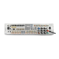
Rear Panel Connections .............................................................................................5
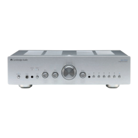
Front Panel Controls ....................................................................................................6
Exploded Diagram ....................................................................................................... 7
Spares Table ................................................................................................................ 8
Front Panel PCB Schematic ........................................................................................9
Front Panel PCB Layout ............................................................................................10
Front Panel PCB BOM ...............................................................................................11
Input PCB Schematic ................................................................................................12
Input PCB Layout ....................................................................................................... 14
Input PCB BOM ..........................................................................................................15
Preamp PCB Schematic ............................................................................................ 17
Preamp PCB Layout ..................................................................................................20
Preamp PCB BOM .....................................................................................................21
Protection PCB Schematic ........................................................................................23
Protection PCB Layout ..............................................................................................24
Protection PCB BOM .................................................................................................25
Speaker PCB Schematic ...........................................................................................26
Speaker PCB Layout ..................................................................................................28
Speaker PCB BOM ....................................................................................................29
Power Amp PCB Schematic ......................................................................................30
Power Amp PCB Layout .............................................................................................35
Power Amp PCB BOM ................................................................................................36
Mains PCB (EU) Schematic .......................................................................................38
Mains PCB (EU) BOM ................................................................................................39
Mains PCB (CU) Schematic ......................................................................................40
Mains PCB (CU) BOM ................................................................................................41
Mains PCB Layout .....................................................................................................42
USB Input Audio PCB Schematic ..............................................................................43
USB Input Audio PCB Layout ....................................................................................44
USB Input Audio PCB BOM .......................................................................................45
IC Details ....................................................................................................................47
Include APD changes
Revised Part Table and explanation of APD changes ..............................................55
Input PCB Schematic with APD .................................................................................56
Preamp PCB Schematic with APD .............................................................................58
AMP PCB Schematic ..................................................................................................61
Switched Mode Power Supply Schematic ................................................................66
Auto Power Down Trigger board schematic ..............................................................67
Auto Power Down(Trigger) Gerbers ...........................................................................68
APD Trigger Cable .......................................................................................................70