3199ZBX6
www.came.com
FA00042M4A
- ver.
- 05/2015
FA00042M4A
Italiano
IT
English
EN
Français
FR
Русский
RU
ITALIANO
Avvertenze generali
• Prima di installare la scheda ed e ettuare i collegamenti elettrici, compreso l’inserimento di schede a innesto (AF, R700,
etc), è OBBLIGATORIO TOGLIERE LA TENSIONE DI LINEA e, se presenti, scollegare le batterie.
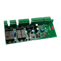
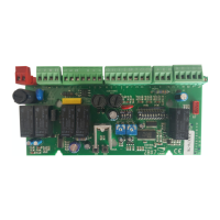
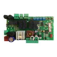
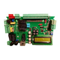
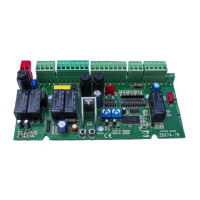
Descrizione
Ricambio per scheda elettronica ZBX6.
Collegamenti
L1 - L2 Alimentazione 230 V AC
10 - 11
Uscita 24 V AC - 20 W max
U - W - V
M
Motoriduttore a 230 V AC
W - E1
Lampeggiatore 230 V AC - 25 W max
11 - FC
Lampada spia cancello aperto 24 V AC - 3 W max
11 - FA
Spia cancello chiuso 24 V AC - 3 W max
1 - 2
Pulsante di STOP (contatto NC)
⚠ Se non utilizzato ponticellare 1-2
2 - 7
Pulsante di comando APRE-CHIUDE-INVERSIONE (contatto NO)
F - FA
Finecorsa in apertura (contatto NC)
F - FC
Finecorsa in chiusura (contatto NC)
2 - C1
Collegamento fotocellule in riapertura durante la chiusura (contatto NC)
⚠ Se non utilizzato ponticellare 2-C1
Antenna
Per una descrizione più dettagliata dei collegamenti elettrici e delle funzioni, consultare il manuale di riferimento su http://
docs.came.com.
Attivazione del comando radio
⚠ Togliere la tensione e, se presenti, scollegare le batterie.
- Collegare il cavo TOP-RG58 dell’antenna.
- Inserire la scheda af sulla scheda elettronica.
- La scheda elettronica riconosce la scheda af solo quando viene ridata tensione.
- Tenere premuto il tasto PROG o CH1 sulla scheda elettronica, il LED di segnalazione lampeggia.
- Premere un tasto del trasmettitore per inviare il codice, il LED cambia stato a segnalare l’avvenuta memorizzazione.
Funzioni
DIP 1 OFF AZIONE MANTENUTA disattivata (ON attivata, esclude funzionamento trasmettitore)
DIP 2 ON
CHIUSURA AUTOMATICA attivata
Il tempo di attesa prima della chiusura è regolabile. Si esclude dopo un comando di STOP TOTALE o in
caso di blackout (OFF - disattivata)
Regolazioni trimmer
TRIMMER TCA: regolazione del tempo di attesa prima della CHIUSURA AUTOMATICA: da 1 a 120 s.
Limitatore di coppia
Spostare il FASTON su una delle 4 posizioni: min 1 - max 4.
Dismissione e smaltimento. I componenti dell’imballo (cartone, plastiche, etc.) sono assimilabili ai rifi uti solidi urbani. I componenti del
prodotto (metalli, schede elettroniche, batterie, etc.) vanno separati e di erenziati. Per le modalità di smaltimento verifi care le regole vigenti
nel luogo d’installazione. Non disperdere nell’ambiente!
I CONTENUTI DEL MANUALE SONO DA RITENERSI SUSCETTIBILI DI MODIFICA IN QUALSIASI MOMENTO SENZA OBBLIGO DI PREAVVISO.
ENGLISH
General warnings
• Before installing the control board and making the electrical connections, including fi tting the snap-in (AF, R700, etc.), IT
IS OBLIGATORY TO CUT OFF THE MAINS POWER, and, disconnect any batteries.
Description
Spare ZBX6 control board.
Connections
L1 - L2 Power supply 230 V AC
10 - 11
24 V AC - 20 W max output
U - W - V
M
230 V AC gearmotor
W - E1
230 V AC - 25 W max flashing light
11 - FC
24 V AC - 3 W max gate open warning light
11 - FA
Gate closed warning light 24 V AC - 3 W max
1 - 2
STOP button (NC contact)
⚠ If unused bridge 1-2
2 - 7
OPEN-CLOSE-INVERT (NO contact)
F - FA
Opening limit switch (NC contact)
F - FC
Closing limit switch (NC contact)
2 - C1
Photocells reopening during closing connection (NC contact)
⚠ If unused bridge 2-C1
Antenna
For a more detailed description of the electrical connections and functions, please read the reference manual on http://docs.came.com.
Activating the radio control
⚠ Cut o the mains power and, if present, remove and batteries.
- Connect the TOP-RG58 antenna cable.
- Fit the AF card into the control board.
- The control board recognizes the AF card only when the power is switched back on.
- Keepthe PROG or CH1 key pressed on the control board, the warning LED fl ashes.
- Pressa key on the transmitter to send the code, the LED changes status to signal that memorization has been successful.
Functions
DIP switches 1 OFF MAINTAINED ACTION deactivated (ON activated, excludes the transmitter's operation)
DIP switch 2 ON
AUTOMATIC CLOSING activated
The waiting time of the fi rst closing is adjustable. It is excluded after a TOTAL STOP command or
in case of a power outage (OFF - deactivated)
Trimmer adjustments
ACT TRIMMER: adjusting the waiting time before AUTOMATIC CLOSING: from 1 to 120 s.
Torque limiter
Move the FASTON to one of the four positions: 1 min - 4 max..
Decommissioning and disposal. - The packaging materials (cardboard, plastic, and so on) should be disposed of as solid household waste.
The product components (metals; control boards, batteries, etc.) must be separated from other waste for recycling. Check your local laws to
properly dispose of the materials.Do not dispose of in nature!
THE CONTENTS OF THIS MANUAL MAY BE REVISED AT ANY TIME, AND WITHOUT NOTICE.