Page 7 - Manual FA01560-EN - 02/2023 - © CAME S.p.A. - The contents of this manual may be changed at any time and without notice. - Translation of the original instructions
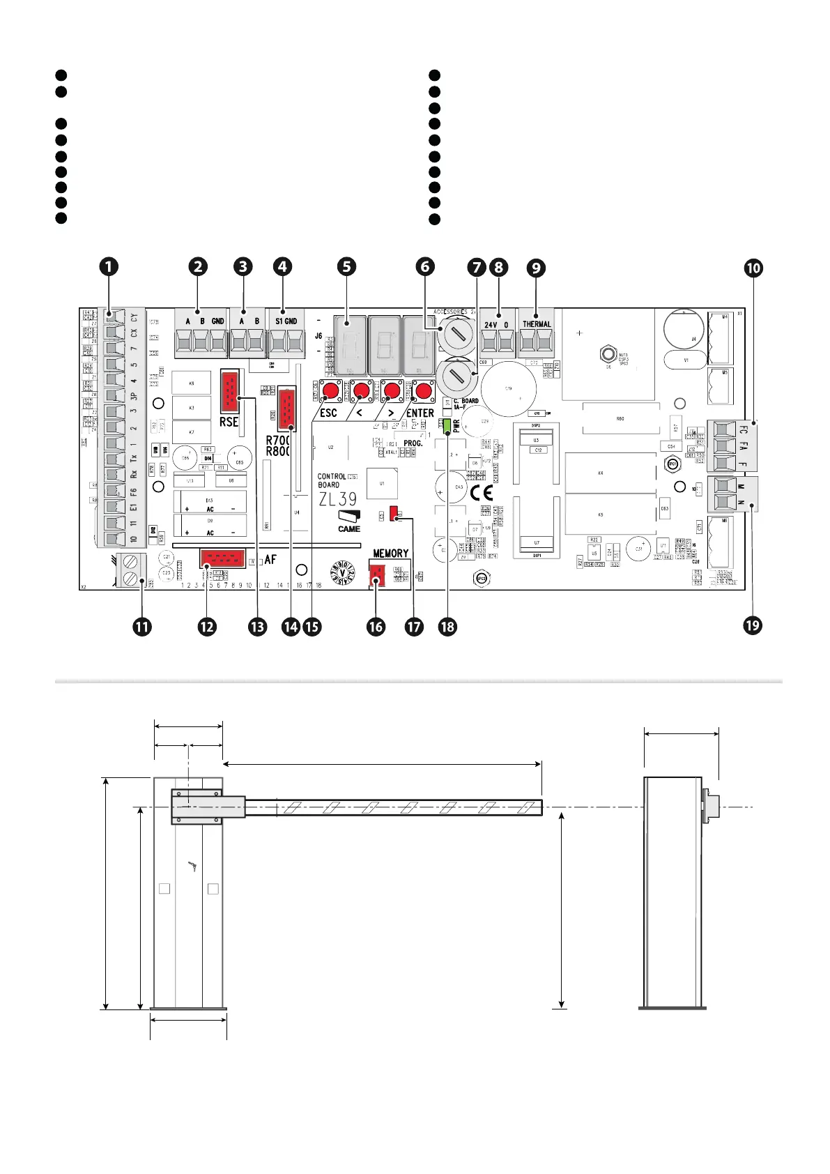
Control board ZL39B
1
Terminal board for connecting control and safety devices
2
Terminal board associated with the RSE connector for paired, alternate or CRP
connection
3
Terminal board for connecting the keypad selector
4
Terminal board for connecting the transponder selector switch
5
Display
6
Accessories fuse
7
Control board fuse
8
Terminal board for connecting the transformer
9
Terminal board for connecting the transformer thermal cut-off switch
10
Terminal board for limit-switch micro-switches
11
Terminal board for connecting the antenna
12
Connector for plug-in radio frequency card (AF)
13
RSE card connector
14
Connector for the R700 or R800 decoding card
15
Programming buttons
16
Memory Roll card connector
17
Programming status warning LED
18
Power LED
19
Terminal board for motor power supply
Size
884
1007
884
max. 4000
260
==
265
270

 Loading...


