- pag. - pag.
- pag. - pag.
- pag.
44
44
4
- english - - english -
- english - - english -
- english -
DESCRIPTION OF ASSEMBLY PROCEDURE
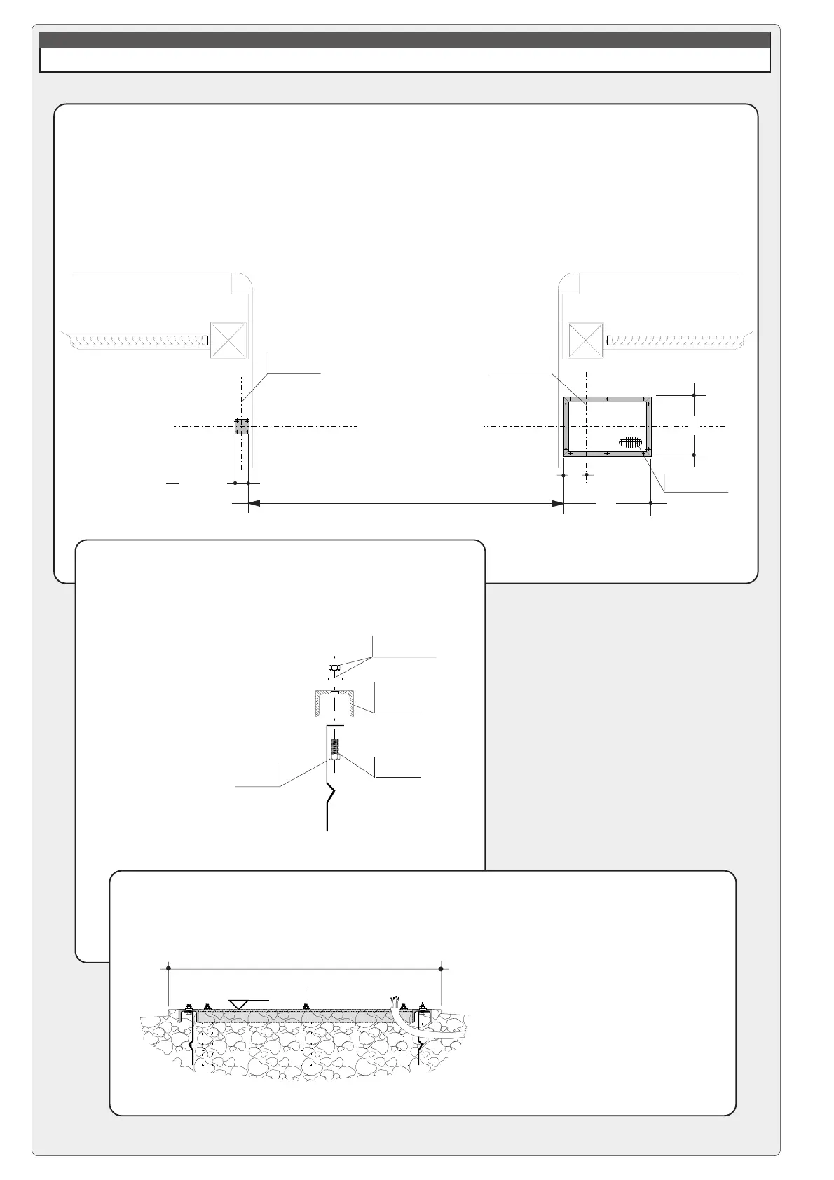
1 - ASSEMBLY OF FIXED STRUCTURES, MARKING
a) determine the desired positions
for the housing as well as for the
fixed support for the barrier bar;
mark the longitudinal and
transverse axes of the barrier.
c) Sink everything into the
relative cement bases. Be
sure that the mounting base is
perfectly level, and that the
electrical cables for the unit
protrude in the area indicated.
b) detach the mounting base
from the housing and mount
the anchor stays on the base;
apply grease and/or removable
tape to protect the threaded
bolts protruding from the top.
anchor
screw
mounting nut
and washer
UNP 65x42
profile of
mounting base
profile of cement base
580
120 x 120
axis of
barrier bar rotation
axis of support
for barrier bar
longitudinal axis of barrier
recommended
area for cable exit
235
865
LN = USEFUL NET WIDTH OF PASSAGE = 11850 mm MAX
6500 mm MIN
anchor stay

 Loading...