COLLEGAMENTO ABBINATO I MATCHING CONNECTIONS I BRANCHEMENT ACCOUPLE
KOMBIANSCHLUSS/CONEXI6N COMBINADA
c
10N
SON
MORSETTlERA
"OlORE
2
-K'TDR
2
TERMINAL BlOCK
PLAQUE
it.
BORNE! MClEUR 2
KlEMMBRETT MOTOR
2
CUADRO DE BORNES MOTOR
2
...•
- -
.
".
"Slave"
"Master"
[101
1__
1
~~ZP10
~ 111111
I
[101
1__
1
m
", :~ZP10
I
111111
I
J
MORSEITJERA
..aTOM 1
MOTOR
1
TERMIIVAl BlOCK
PLAQUE
A
BORNE! MOTEUR
1
KlEMMBRErT MOTOR
f
CUADRO DE BORNES MOTOR
1
(ITALIANO)
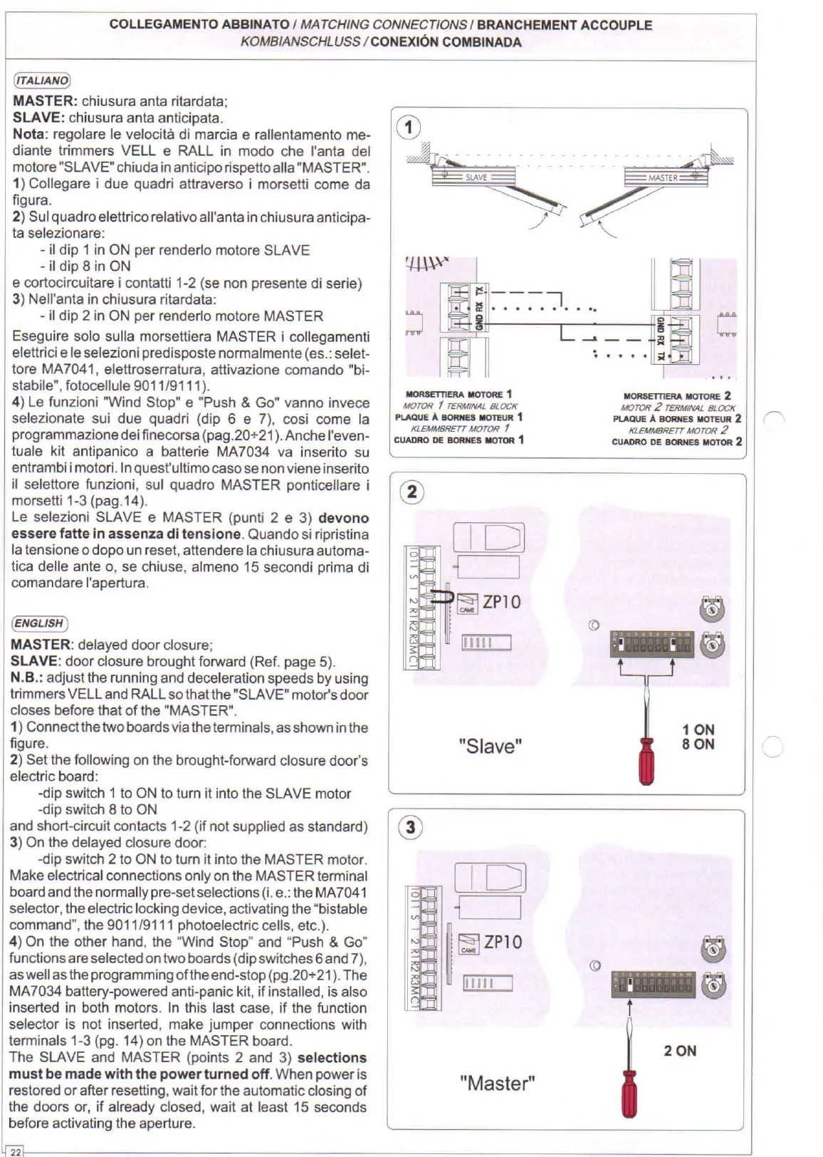
MASTER: chiusura anta ritardata;
SLAVE: chiusura anta anticipata.
Nota: regolare Ie velocita di marcia e rallentamento me-
diante trimmers VELL e RALL in modo che I'anta del
motore "SLAVE" chiuda in anticipo rispetto alia "MASTER".
1) Collegare i due quadri attraverso i morselli come da
figura.
2) Sui quadro elellrico relativo all'anta in chiusura anticipa-
ta selezionare:
- il dip 1 in ON per renderlo motore SLAVE
- iI dip 8 in ON
e cortocircuitare i contalli 1-2 (se non presente di serie)
3) Nell'anta in chiusura ritardata:
- iI dip 2 in ON per renderlo motore MASTER
Eseguire solo sulla morsetliera MASTER i collegamenti
elellrici e Ie selezioni predisposte normalmente (es.: selet-
tore MA 7041, elellroserratura, allivazione comando "bi-
stabile", fotocellule 9011/9111).
4) Le funzioni "Wind Stop" e "Push & Go" vanno invece
selezionate sui due quadri (dip 6 e 7), cosi come la
programmazione dei finecorsa (pag.20+21). Anche I'even-
tuale kit antipanico a ballerie MA7034 va inserito su
entrambi i motorl.lnquest'ultimo caso se non viene inserito
iI selellore funzioni, sui quadro MASTER ponticellare i
morselli 1-3 (pag.14).
Le selezioni SLAVE e MASTER (punti 2 e 3) devono
essere fatte in assenza di tensione. Quando si ripristina
la tensione
0
dopo un reset, allendere la chiusura automa-
tica delle ante
0,
se chi use, almeno 15 secondi prima di
comandare I'apertura.
(ENGLISH)
MASTER: delayed door closure;
SLAVE: door closure brought forward (Ref. page 5).
N.B.: adjust the running and deceleration speeds by using
trimmers VELL and RALL so that the "SLAVE" motor's door
closes before that of the "MASTER".
1) Connect the two boards via the terminals, as shown in the
figure.
2) Set the following on the brought-forward closure door's
electric board:
-dip switch 1 to ON to turn it into the SLAVE motor
-dip switch 8 to ON
and short-circuit contacts 1-2 (if not supplied as standard)
3) On the delayed closure door:
-dip switch 2 to ON to turn it into the MASTER motor.
Make electrical connections only on the MASTER terminal
board and the normally pre-set selections (I. e.: the MA7041
selector, the electric locking device, activating the "bistable
command", the 9011/9111 photoelectric cells, etc.).
4) On the other hand, the "Wind Stop" and "Push & Go"
functions are selected ontwo boards (dip switches 6 and 7),
aswell as the programming of the end-stop (pg.20+21). The
MA7034 ballery-powered anti-panic kit, if installed, is also
inserted in both motors. In this last case, if the function
selector is not inserted, make jumper connections with
terminals 1-3 (pg. 14) on the MASTER board.
The SLAVE and MASTER (points 2 and 3) selections
must be made with the power turned off. When power is
restored or after reselling, wait for the automatic closing of
the doors or, if already closed, wait at least 15 seconds
before activating the aperture.
"
 Loading...