-7-
QUADRO COMANDO -
CONTROL PANEL
- ARMOIRE DE COMMANDE -
SCHALTTAFEL
- CUADRO DE MANDO
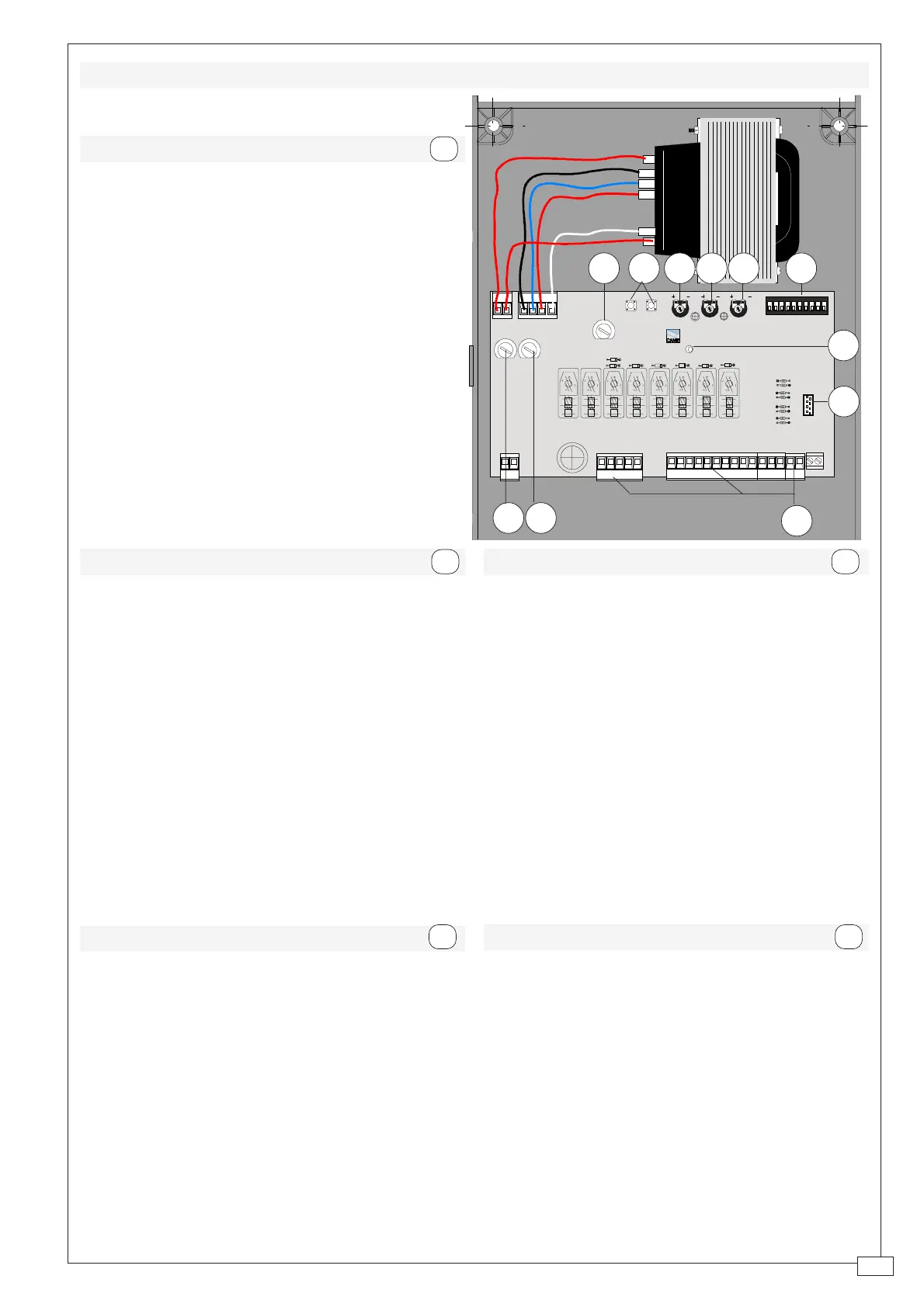
PRINCIPALES COMPONENTES
1 Caja de bornes las conexiónes
2 Fusible de línea 1.6A
3 Fusible para central 1.6A
4 Indicador luminoso
5 Teclas memorización códigos
6 Trimmer de regulación tiempo trabajo
7 Trimmer de regulación tiempo cierre
automático
8 Trimmer de regulación retraso cierre 2°
motor y apertura parcial
9 Selector de funciones con 10 dip (vedas
pag.10)
10 Conexión tarjeta radiofrecuencia (ver
tabla)
11 Fusible motor/electrocerradura 5A
E
HAUPTKOMPONENTEN
1 AnschlußKlemmenleiste
2 Hauptsicherung 1.6A
3 Schaltkastensicherung 1.6A
4 LED Kontrolleuchte zur Anzeige
5 Code-Speichertasten
6 Trimmer zur Einstellung Laufzeit
7 Trimmer zur Einstellung der Schließ-
automatik
8 Trimmer zur Einstellung Schließverzöger-
ung Motor 2 und Teilweises Öffnung
9 Wählschalter für Funktionen mit 10 Dip
(sehen S.10)
10 Steckanschluß Funkfrequenze-Platine
(sehen Tabelle)
11 Elektroschloß/Motorsicherung 5A
D
PRINCIPAUX COMPOSANTS
1 Plaque à bornes de connexion
2 Fusible de ligne 1.6A
3 Fusible boîtier 1.6A
4 LED de signalisation
5 Boutons-poussoir mémorisation code ra-
dio
6 Trimmer de réglage temps de fonction-
nement
7 Trimmer de réglage fermeture automa-
tique
8 Trimmer de réglage retard fermeture
moteur 2à et ouverture partielle
9 Selecteur de fonctions à 10 interrupteurs
à positions multiples (voir pag.9)
10 Branchement carte radiofréquence (voir
tableau)
11 Fusible moteur/serrure électrique 5A
F
MAIN COMPONENTES
1 Terminal block for external conections
2 1.6A line fuse
3 1.6A central control unit fuse
4 Signal LED
5 Radio-code save buttons
6 Trimmer for adjustment operating time
7 Trimmer for adjustment automatic closing
8 Trimmer for adjustment delay on closing
cycle motor n°2 and partial opening
9 10-dip function switch (see p.9)
10 Radiofrequency board socket (se table)
11 5A motor/electric lock fuse
GB
AF
ZL150
QUADRO COMANDO
T.L. T.C.A.
AP.PARZ.
2
1 345678910
ON
FUSIBILE
LINEA 5A
FUSIBILE
CENTR. 1.6A
01524 20L1T L2T
FUSIBILE
MOTORE/SERR. 5A
33
33
3
22
22
2
11
11
1
55
55
5
66
66
6
77
77
7
88
88
8
99
99
9
1010
1010
10
44
44
4
1111
1111
11
COMPONENTI PRINCIPALI
1 Morsettiere di collegamento
2 Fusibile di linea 1.6A
3 Fusibile centralina 1.6A
4 LED di segnalazione
5 Pulsanti memorizzazione codice radio
6 Trimmer di regolazione tempo lavoro
7 Trimmer di regolazione tempo in chiusura
automatica
8 Trimmer di regolazione ritardo in chiusura
2° motore e apertura parziale
9 Selettore funzioni a 10 dip (vedi pag. 8)
10 Innesto scheda radiofrequenza (vedi ta-
bella)
11 Fusibile motore/elettroserratura 5A
I
 Loading...