30
Section 4 Model 288A Differential Pressure Indicating Switch
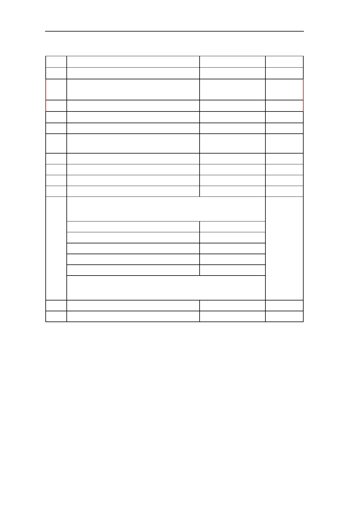
Table 4.1—Parts List, Model 288A Indicating Switch
Item Description Part No. Per Unit
16 Screw, Bezel 9A-C0181-0007C 3
17 Screw, Flat, Skt Cap, 10-32 x 1/2, SST (Riser/
DPU)
9A-C0240-0019J 8
18 Spacer, DPU to case 9A-C0224-1547C 1
19 O-Ring, 2-111, Viton 9A-C0001-0157R 1
20 Stud, Drive-Lok, Retaining, Bezel 9A-C0004-0005K 1
21 Screw, Relay Mtg. Hole Filler (if relay is not
installed, 2 per relay, not shown)
9A-C0111-0007J A/R
22 Ground Wire Assembly, External Wire See Table 4.2, page 33 A/R
23 Ground Screw, Hex HD, 8-32 x 5/16, Grn 9A-C0117-1012J 1
24 Washer, Lock, Internal Tooth, #8, SST 9A-C0003-0066K 1
25 Washer, Lock, ET, #8, SST 9A-C0003-0050K 1
26 Switch and Plate Assembly:
(Tefzel Insulation-Radiation Resistant)
see also item 29
A/R
Low, SPDT 9A-CS666-1200B-N
Low, DPDT 9A-CS401-0184B-N
Low Relay 9A-CS666-0290B-N
Low #1, Independently Adjustable* 9A-CS666-0286B-N
Low #2, Independently Adjustable* 9A-CS666-0287B-N
*Note: If 3 or 4 independently adjustable switches are used, Low #1 is
installed in the upper left position, and Low #2 is installed in the lower right
position.
27 External Wire Assembly, Low See Table 4.2, page 33 A/R
28 External Wire Assembly, High See Table 4.2, page 33 A/R
* Recommended spare part
** If the scale plate is not identifi ed with an SCR number, provide the following infor-
mation:
Square root or linear graduations,
Scale (e.g., 0-100, 25-0-100, etc.)
Number of graduations (linear scales only)
Data (e.g., PSI, bar, inches of water column, meter, etc.)
Additional Notes:
1. A/R indicates as required.
2. When ordering parts, specify serial number of instrument.
3. For 224 DPU parts, refer to Table A.4, page A-18.