8
Section 2 Model 288A Differential Pressure Indicating Switch
IMPORTANT: Arc suppression for inductive loads will prolong the life of the switch
contacts.
IMPORTANT: Due to their size, subminiature switches have small mechanical clear-
ances; therefore, no rating above 250 VAC has been established.
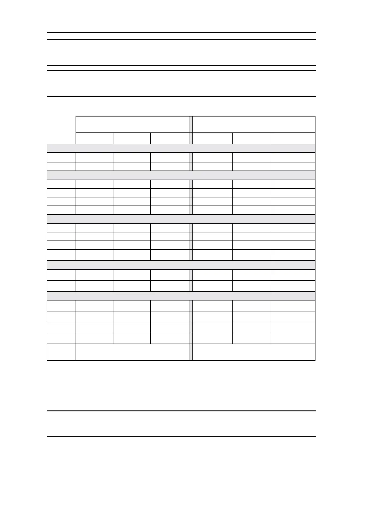
Table 2.1—Switch/Relay Wire Color Coding (4/06c)
288A LEGACY CONFIGURATIONS
(prior to Apr. 2006)
288A CURRENT CONFIGURATIONS
NO C NC NO C NC
SPDT SWITCHES
Low Red Yellow Blue Red Yellow Blue
High Black Green White Black Violet Orange
DPDT SWITCHES
Low #1 Red Yellow Blue Red Yellow Blue
Low #2 White/Red White/Yellow White/Blue White/Red White/Yellow White/Blue
High #1 Black Green White Black Violet Orange
High #2 White/Black White/Green White/Violet White/Black White/Violet White/Orange
4-INDEPENDENTLY ADJUSTABLE SWITCHES
Low #1 Red Yellow Blue Red Yellow Blue
Low #2 White/Red White/Yellow White/Blue White/Red White/Yellow White/Blue
High #1 Black Green White Black Violet Orange
High #2 White/Black White/Green White/Violet White/Black White/Violet White/Orange
SWITCHES FOR RELAYS
Low Red Yellow Blue (Note 1) White/Brown Brown White (Note 1)
High Black Green White (Note 1) White/Gray Gray White (Note 1)
RELAYS
Low #1 Gray Blue Brown Red Yellow Blue
Low #2 White/Gray White/Blue White/Brown White/Red White/Yellow White/Blue
High #1 Violet White Orange Black Violet Orange
High #2 White/Violet White/Black White/Orange White/Black White/Violet White/Orange
Coil
Wiring:
Legacy Ver.: Low = Red and High = Black Current Ver.: Low = White/Brown and High = White/
Gray
Note 1: Wire is NOT connected.
Startup
For startup procedures, warnings, and other information, refer to Appendix A .
IMPORTANT: To ensure the unit calibration is within factory-set calibration tolerances,
perform the Calibration Check procedure on page 15.