9
Model 288A Differential Pressure Indicating Switch Section 2
Switch and Relay Wiring Diagrams
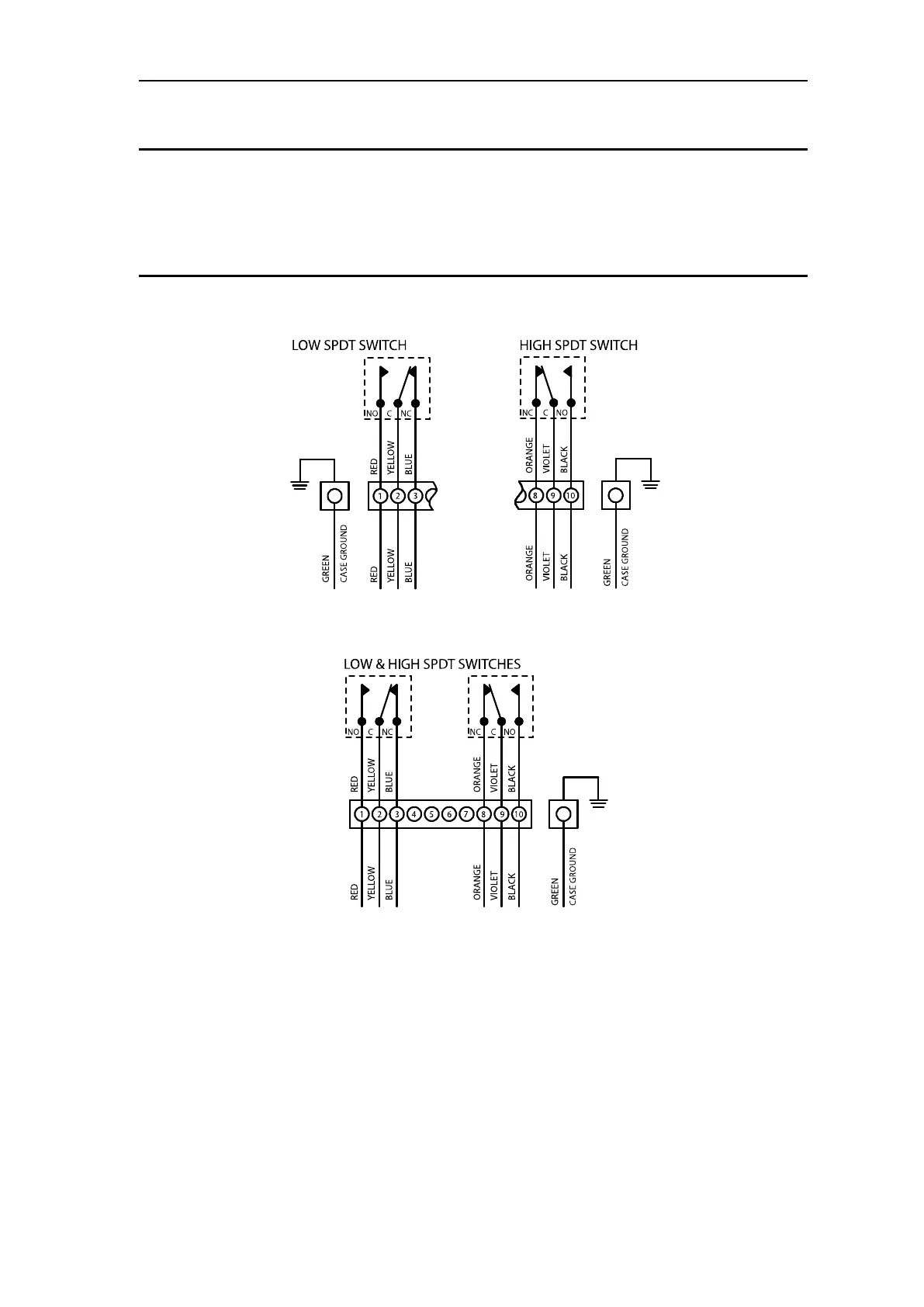
IMPORTANT: Figures 2.1 through 2.6 show: switch & relay contacts in the relaxed
(shelf) condition, the low switch set to trip at a position below the pointer
scale position, and the high switch set to trip at a position above the
pointer scale position. NO = Normally Open in (shelf) condition. NC =
Normally Closed in (shelf) condition. C= Common.
Figure 2.1—Low/high SPDT switch diagrams
(current confi guration color codes - see Table 2.1, page 8)