A-3
Model 224 Differential Pressure Unit Appendix A
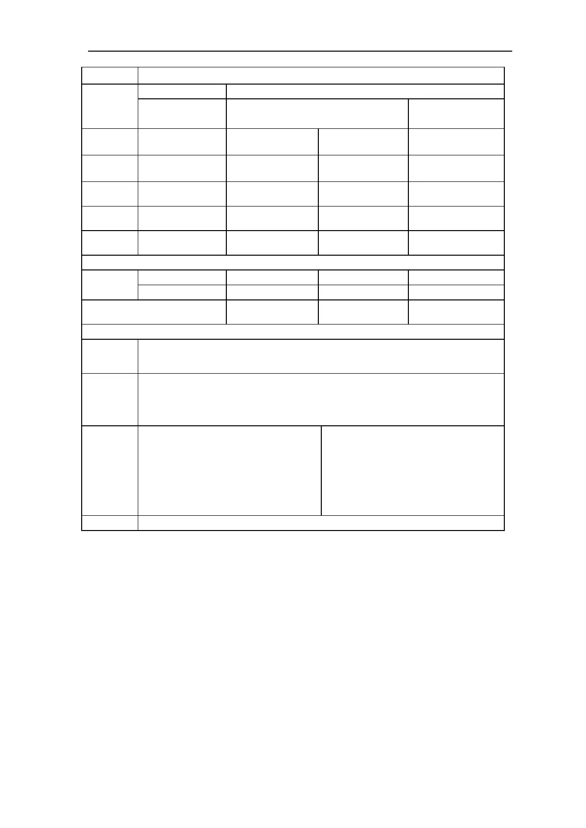
Table A.1—Model 224 DPU Specifi cations
SWP
psi (bar)
BODY AVAILABLE DIFFERENTIAL PRESSURE RANGES
Housing Material
Stainless Steel/Inconel Bellows Inconel Bellows
1-5/8" (41.3 mm) O.D. 3/4" (19.1 mm) O.D. 5/8" (15.9 mm) O.D.
500
(34.5)
Stainless Steel (316)
Copper Nickel (70-30)
0-30" (0-762 mm) w.c.
to 0-60 psi (0-3.8 bar)
0-61 psi (0-3.9 bar) to
0-400 psi (0-27.6 bar)
0-400 psi (0-27.6 bar) to
0-500 psi (0-34.5 bar)
1,000
(68.9)
Copper Nickel (70-30)
(MIL-C-15726)
0-60" (0-1524 mm) w.c.
to 0-60 psi (0-3.8 bar)
0-61 psi (0-3.9 bar) to
0-400 psi (0-27.6 bar)
0-400 psi (0-27.6 bar) to
0-1000 psi (0-68.9 bar)
1,500
(103.4)
Stainless Steel (316) 0-60" (0-1524 mm) w.c.
to 0-60 psi (0-3.8 bar)
0-61 psi (0-3.9 bar) to
0-400 psi (0-27.6 bar)
0-400 psi (0-27.6 bar) to
0-1000 psi (0-68.9 bar)
3,000
(206.9)
Stainless Steel (316) 0-60" (0-1524 mm) w.c.
to 0-60 psi (0-3.8 bar)
0-61 psi (0-3.9 bar) to
0-400 psi (0-27.6 bar)
0-400 psi (0-27.6 bar) to
0-1000 psi (0-68.9 bar)
6,000
(413.8)
Stainless Steel (316) 0-60" (0-1524 mm) w.c.
to 0-60 psi (0-3.8 bar)
0-61 psi (0-3.9 bar) to
0-400 psi (0-27.6 bar)
0-400 psi (0-27.6 bar) to
0-1000 psi (0-68.9 bar)
Net Volume
(cu. in.)
L.P. Head 1.66" (42.2 mm) 2.51" (63.8 mm) 2.61" (66.3 mm)
H.P. Head 1.55" (39.4 mm) 2.42" (61.5 mm) 2.50" (63.5 mm)
Displacement in cu. in. for full-scale
travel
0.14" (3.6 mm) 0.03" (0.8 mm) 0.025" (0.6 mm)
Pressure
Ranges
Zero center or split ranges available on special order (e.g. a 0-60" w.c. (0-1524 mm) range may be
ordered 30-0-30" w.c. (762-0-762 mm) or 15-0-45" w.c. (381-0-1143 mm); Absolute pressure ranges
available from 30" w.c. (762 mm) to 400 psi (41.4 bar).
Pressure
Connections
1/4 NPT top x 1/4 NPT bottom
1/4 NPT top x 1/2 NPT bottom
1/2 NPT top x 1/4 NPT bottom
1/2 NPT top x 1/2 NPT bottom
Performance
Torque Tube Rotations (full- scale DP)
Temperature Limits
Maximum Non-linearity:
0-30" wc to 0-150 psi
0-150 psi to 0-400 psi
0-400 psi to 0-1000 psi
Repeatability
8º ± 10%
-40ºF (-40ºC) to 180ºF (+82ºC)
± 1-1/2%
± 2%
± 4%
± 0.2% of full scale
Dimensions Outline dimension drawings available upon request.
Theory of Operation
The Barton Model 224 DPU shown in Figure A.2, page A-4, measures the diff er-
ential pressure in a process system relative to process functions and produces
a mechanical output that actuates process monitoring instruments and process
control devices.
The high-pressure (HP) housing is connected by pipe or tubing to the high-
pressure side of the primary measuring device. The low-pressure (LP) hous-
ing is connected to the low-pressure side of the primary device.
As pressure changes within the housings, the bellows move laterally. The
connecting drive arm follows the motion of the bellows, and twists the torque
tube. The rotation of the torque tube shaft provides the mechanical motion