16
INSTALLATION
INSTALLATION
#415-R1
8-15-18 - JR
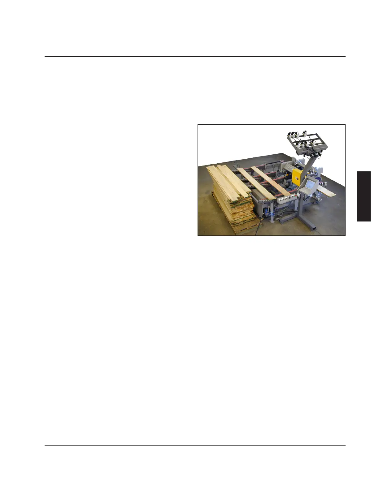
Opti-Rip Assembly
The Opti-Rip has been pre-assembled
and run at our factory, then broken into the
following major components: The machine
section, the laser stand, and the computer
enclosure.
Initial Placement
Position the machine in front of the rip
saw as shown in the layout located in the
"Introduction" section of this manual.
Install the Belt Tracks
On machines made for wider saws, the belt
tracks may have been removed for shipping.
If the belts are already in place, this step
should be skipped.
When installing the belt tracks, make sure
to loop a belt over each belt track before
bolting it in place. Otherwise, you will not
be able to attach the belts. Each belt track
attaches to the infeed legs and outfeed
legs with the shallow side up. Note that the
tracks are numbered.
When mounting track number 1, also install
the light curtain mounting brackets in their
proper position. When mounting track
number 3, also mount the guard for the drive
belt.
Tension the belts so that each belt hangs
down 1/8" below the bottom of the belt track
in the center. You may notice that there is
a 1/32" shim between the idler bracket and
the belt track on the bolt nearest the end of
the track. This will angle the idler out slightly
so that when the belt is in tension, it will
be pulled back square again. This shim is
 Loading...