2.3.5 Outside air intakes
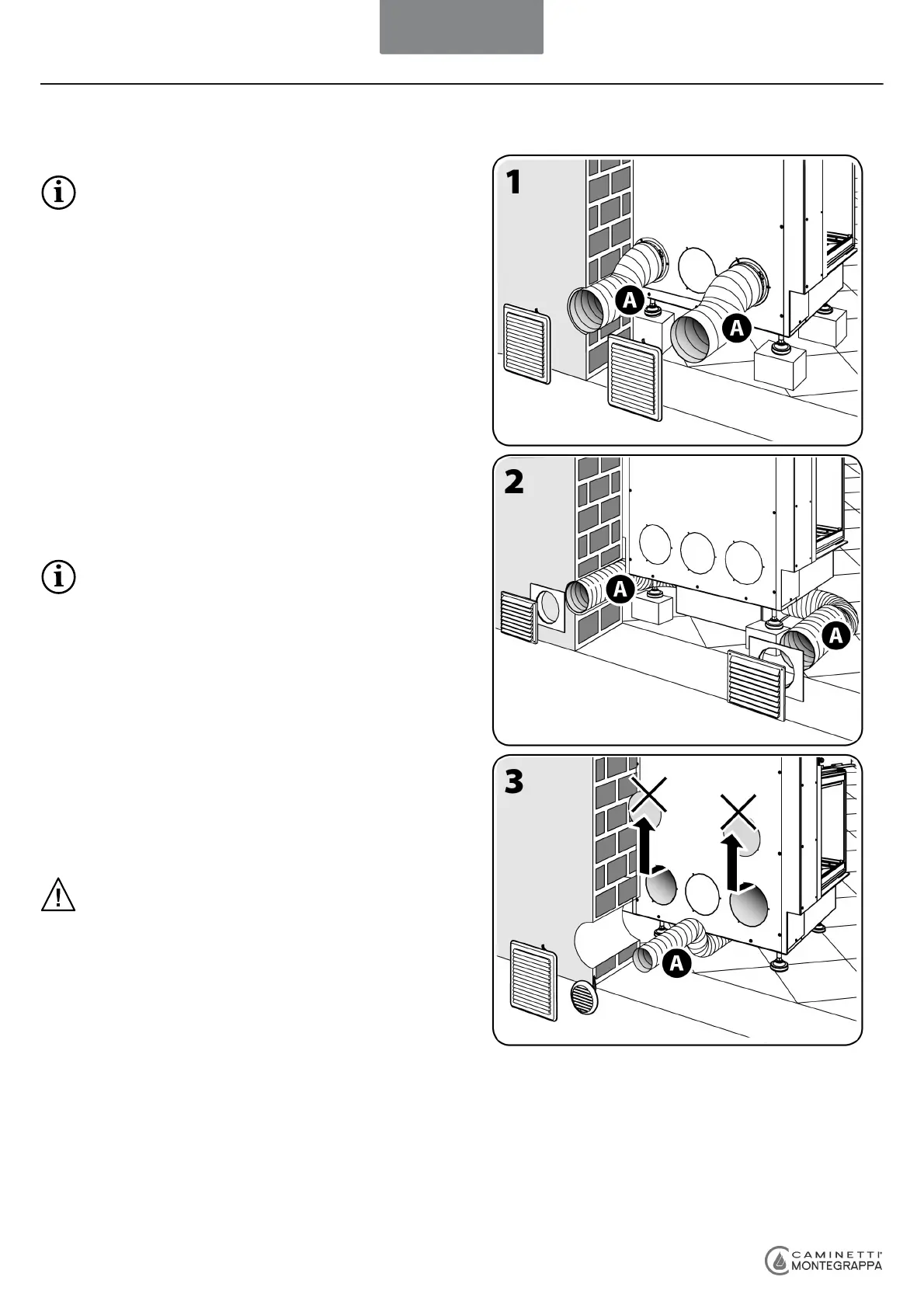
The appliance, to intake air from outdoors, can also be installed simply with just the primary air channelling. Apply the intake
under the appliance and insert the section of flexible aluminium pipe [A] Ø 8 cm in it and secure with a pipe collar.
Make two holes in the wall communicating with the outdoors (or with a sufficiently aerated room) suitable for feeding the relevant
flexible aluminium pipe Ø 8 cm and another of Ø 15 cm inside the drywall panel (see figure 3).
Once the appliance has been positioned correctly as just described, insert the collector into the section of flexible aluminium pipe
[A] and fix it with the collar, then insert the piep section into the hole made previously. Now mount the 2 PVC louvers, one on the
flexible pipe Ø 8 cm and the other on the Ø 15 cm hole.
Consult the pictures in sections 1.8.2, 1.8.3 and 1.8.4
carefully.
The standards currently in force require that all appliances be
equipped with pipes of adequate dimensions to admit into the
firebox an outside air flow ensuring an efficient and complete
combustion of wood.
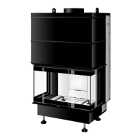
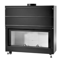
For this appliance to function as a warm air generator with the
"Natural Convection" or "Forced convection" system and at the
same time to reinstate the oxygen burnt during combustion, it
has 3 (use just 2) 15 cm Ø external air intakes (for natural
convection, see figure 1) located at the back of the appliance
and 2 intakes 12 cm Ø (for forced convection, see figure 2), one
on the right and one on the left side of the fan box.
Mount the two relevant sections of flexible aluminium pipes [A]
in these intakes and secure them with 2 pipe collars.
Make two holes in the wall communicating with the outdoors
(or with a sufficiently aerated room) suitable for feeding the
relevant flexible aluminium pipes (see figures 1 and 2).
Move the appliance, lifting or pushing it and sliding it on the
base of the fan box over suitable floor protection.
Since the appliance is very heavy, take due
precautions if moving on wood floor.
Place the appliance 12 cm away from the wall (or from the
protection masonry in case the walls are made of combustible
materials) and in the definitive position (check the dimensions
of the cladding to install in order to determine the exact
position).
Lift the appliance back on the raising elements once and for all
and adjust its height and the levels by turning the adjustable
feet (using 10-mm spanner); the feet can also be accessed from
inside the appliance from under the hearth.
Insert the 2 aluminium lengths of flexible pipe [A] into the holes
previously made and cut them in line with the outside wall.
Mount the 2 PVC protection louvers on the afore-mentioned
pipes; safe operation and high performance are ensured by
using the air intakes supplied with the appliance.
IMPORTANT: Check regularly that the air intakes are
not obstructed (a flow of air of 170 cm² should always
be guaranteed through each louver, for natural
convection appliances, and 100 cm² for forced
convection appliances).
ENGLISH
TECH 3
25
 Loading...