Do you have a question about the Campbell AVW200 series and is the answer not in the manual?
Reduces external noise and improves readings using spectral analysis.
Explains AVW200's compatibility with Campbell Scientific dataloggers.
Details using PakBus protocol with AVW200 via RS-232.
Covers PakBus protocol with wireless AVW200 models.
Explains SDI-12 communication for older dataloggers.
Covers using DevConfig, LoggerNet, and Terminal Commands with AVW200.
Explains spectral approach for measuring vibrating wire sensors.
Measures internal thermistor resistance for temperature correction.
Steps for connecting AVW200 directly to a datalogger via RS-232.
Details connecting AVW206/211/216 wirelessly to a datalogger.
Steps for connecting multiplexers to AVW200 via direct RS-232.
Details connecting multiplexers wirelessly via AVW206 and RF401.
Describes using SDI-12 for sensors with datalogger-controlled multiplexers.
Explains direct sensor connection to the AVW200.
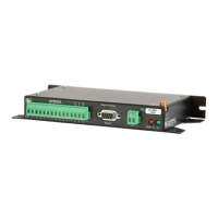
Details proper power and ground connections for the AVW200.
Lists options for connecting AVW200 directly to dataloggers.
Explains connecting antennas to wireless AVW200 models.
Describes wiring for AVW200 to control multiplexers.
Explains wiring for datalogger control of multiplexers via SDI-12.
Steps to connect the AVW200 to a PC for configuration using DevConfig.
Details the Deployment Communications Editor settings for RF communication.
Configures SDI-12, multiplexers, and measurement frequencies in DevConfig.
Describes using the Data Monitor tab to view Public or Status tables.
Instructions for downloading a new operating system to the AVW200 using DevConfig.
Explains using the Troubleshoot tool in DevConfig to evaluate sensor spectra.
Notes that Settings Editor is used for Deployment parameters.
Details using terminal commands to monitor the AVW200.
Explains the CRBasic AVW200() instruction for reading sensor data.
Explains how the AVW200 instruction runs in pipeline mode for measurements.
Details how the AVW200 instruction operates in sequential mode.
Using SDI-12 instruction for measurements with specific dataloggers.
Details the SDI12Recorder instruction and its parameters.
Explains extended SDI-12 commands for changing measurement parameters.
Notes datalogger must control multiplexers in SDI-12 mode.
Example program for direct RS-232 connection with two sensors.
Example program for wireless connection and temperature conversion.
Example program for controlling two multiplexers using AVW200.
Example program demonstrating AVW200 instruction in pipeline mode.
Example programs for AVW200 instruction in sequential mode.
Example for AVW200 controlling two multiplexers in sequential mode.
Example for datalogger controlling multiplexers in sequential mode.
Example program for running AVW200 using SDI12Recorder instruction.
Troubleshooting steps for communication issues with DevConfig or terminal.
Verifying datalogger communication with the AVW200.
Common causes and solutions for wireless connection problems.
Demonstrates converting Hertz to displacement using calibration data.
Explains using the Steinhart-Hart equation to convert resistance to Celsius.
Discusses factors affecting temperature measurement accuracy.
Lists FCC authorized antennas compatible with wireless AVW200 models.
Details antenna cables required for specific antennas.
Lists components of the Surge Protector Kit for RF401 radios.
Warns about FCC compliance and potential interference issues.
Describes fields and control parameters in the AVW200 public table.
Provides a CRBasic program to force a measurement and retrieve data.
Lists and describes status table variables accessible via DevConfig or datalogger.
Shows examples of good sensor measurements with varying frequency ranges.
Illustrates how to deal with noise using frequency range adjustments.
Example of CR1000 controlling AVW200 and two multiplexers via RS-232.
Example of CR1000 communicating with AVW206 via RF401 for sensors with different frequencies.
Example of CR1000 controlling AM16/32 multiplexers directly.
Explains DevConfig settings needed for AVW200 and MD485 modems.
Details point-to-point and point-to-multipoint MD485 network configurations.
Describes using null modem cable to connect datalogger to MD485.
Explains connecting MD485 units using CABLE2TP cable and grounding.
Describes connecting MD485 to AVW200 using a null modem cable.
Notes AVW200 must control multiplexers in this configuration.
Provides an example network setup and CR1000 program for MD485 communication.
| Brand | Campbell |
|---|---|
| Model | AVW200 series |
| Category | Analytical Instruments |
| Language | English |