AVW200-series 2-Channel Vibrating Wire Spectrum Analyzer Modules
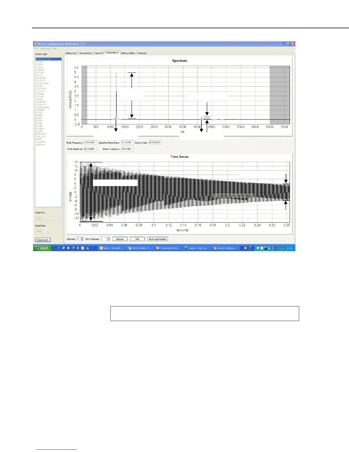
Response
Amplitude
Noise Amplitude
Resonant Frequency
Noise Frequency
Beginning Amplitude
Ending Amplitude
FIGURE 2.1-2. DevConfig plots showing the AVW200 measurement approach.
Please note that the use of the special FFT algorithm to achieve better noise
immunity does require time for computation, which limits the maximum
vibrating wire measurement rate to 2 seconds per sensor. Running a program
at rates faster than this will result in compile/download errors.
Read more! You can find Troubleshoot tool information in Section 5.5 and
Appendix F; and detailed programming information in Section 6.
2.2 Temperature
The AVW200 contains a completion resistor for measuring the internal
thermistor contained in many vibrating wire sensors. The thermistor’s
resistance changes with the internal temperature of the sensor. This
temperature can be used to correct errors in the vibrating wire measurement
due to thermal expansion/contraction of the sensor body. The temperature
correction is often used when the temperature of the medium that the sensor is
measuring is changing (e.g. water temperature in a river or shallow lake).
Temperature is calculated by applying the resistance to a known equation such
as the Steinhart-Hart equation. The Steinhart-Hart coefficients for your sensor
are found in the sensor’s user manual.
10
 Loading...