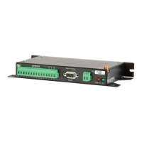
AVW200-series 2-Channel Vibrating Wire Spectrum Analyzer Modules
For example, the following AVW200() instructions can be used to control
the multiplexers:
AVW200(Data1(),ComSDC7,200,200,mux1(1,1),1,1,16,450,3000,2,_60HZ,1,0)
AVW200(Data2(),ComSDC7,200,200,mux2(1,1),2,1,16,450,3000,2,_60HZ,1,0)
Where,
RF401 = configured for SDC7
Each multiplexer has 16 sensors connected to it.
Begin Frequency = 450
End frequency = 3000
Excitation voltage = 12 V peak to peak (option 2)
Read more! A thorough description of the AVW200() instruction and its
parameters is provided in Section 6.1. A complete example program that
controls two multiplexers is included in Appendix H.1.2.
3.3 Multiplexers Controlled by Datalogger
3.3.1 SDI-12 Communication
Cable that Comes with Sensor
CABLE4CBL Cable
CABLE3CBL Cable
19246 Power Cable
AVW200
Multiplexer
Power
Supply
Datalogger
Sensors
For this example configuration, SDI-12 is used to measure the vibrating wire
sensors. The vibrating wire sensors are attached to multiplexers, which are
controlled by the datalogger.
(1) When using SDI-12, multiplexers have to be controlled by
the datalogger.
NOTES
(2) SDI-12 is the only option available for our CR10X, CR23X,
and CR5000 dataloggers.
(3) SDI-12 is the only option available for non-Campbell
Scientific dataloggers.
17
 Loading...