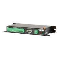
AVW200-series 2-Channel Vibrating Wire Spectrum Analyzer Modules
4. Create a CRBasic program that includes an AVW200() instruction for each
of the sensors.
Check the manufacturer’s specification for the sensors frequency
and excitation range before picking the begin/end frequencies
and excitation voltage.
NOTE
For example, the following AVW200() instructions can be used to
measure two sensors:
AVW200(Result,Com1,200,200,Dst(1,1),1,1,1,1000,3500,2,_60HZ,1,0)
AVW200(Result,Com1,200,200,Dst(2,1),2,1,1,1000,3500,2,_60HZ,1,0)
Where,
AVW200 connects to datalogger control ports 1 & 2 via 17855 cable
(option Com1)
Begin Frequency = 1000
End frequency = 3500
Excitation voltage = 12 V peak to peak (option 2)
Read more! A thorough description of the AVW200() instruction and its
parameters is provided in Section 6.1. A complete example program that
measures two vibrating wire sensors (no multiplexer) is included in
Section 7.1.1.
3.1.2 Wireless Connection
Cable that Comes with Sensor
19246 Power Cable
SC12 CS I/O Cable
Wireless Connection
Sensors AVW206
Sensors
Power
Supply
Datalogger RF401
Onsite
Office
For this example configuration, the sensor(s) are attached directly to the
AVW206. The AVW206 interface transmits the data to an RF401 spread
spectrum radio that is connected to the datalogger.
At the AVW206 site, do the following steps:
1. Configure the AVW206 for RF communications as described in Sections
5.1 and 5.2.1.
12

 Loading...