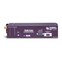
TDR100
1: If Flag/Port (P91)
1: 21 Do if Flag 1 is Low
2: 0 Go to end of Program Table
;Measure the datalogger power supply voltage:
2: Batt Voltage (P10)
1: 1 Loc [ Bat_Volt ]
;Measure the internal temperature of the datalogger:
3: Internal Temperature (P17)
1: 2 Loc [ DL_Temp ]
;Set port 5 high to switch ON "Switched 12V" power from the datalogger to power the TDR100.
4: Do (P86)
1: 45 Set Port 5 High
;Measure the CS610 probe connected to Channel 3 of the level 1 SDMX50 and return La/L.
5: TDR100 Measurement (P119)
1: 0 SDM Address
2: 0 La/L
3: 3001 MMMP Mux & Probe Selection
4: 4 Waveform Averaging
5: 1 Vp
6: 250 Points
7: 9.5 Cable Length (meters)
8: 5 Window Length (meters)
9: .3 Probe Length (meters)
10: .085 Probe Offset (meters)
11: 3 Loc [ LaL_CH3 ]
12: 1.0 Mult
13: 0.0 Offset
;Square La/L to convert to dielectric constant:
6: Z=X*Y (P36)
1: 3 X Loc [ LaL_CH3 ]
2: 3 Y Loc [ LaL_CH3 ]
3: 4 Z Loc [ WC_CH3 ]
;Multiply the dielectric constant by 0.1 to prepare for the 3rd order polynomial
;with the appropriately scaled coefficients for Topp's calibration:
7: Z=X*F (P37)
1: 4 X Loc [ WC_CH3 ]
2: 0.1 F
3: 4 Z Loc [ WC_CH3 ]
41

 Loading...