Connection
To safely use of CSPF-100, it is important that people installing or handling it, follow the usual
safety precautions.
• Care must be taken with the capacitors, which may be charged and may discharge even after
voltage is removed. Ensure that the capacitors have had time to discharge.
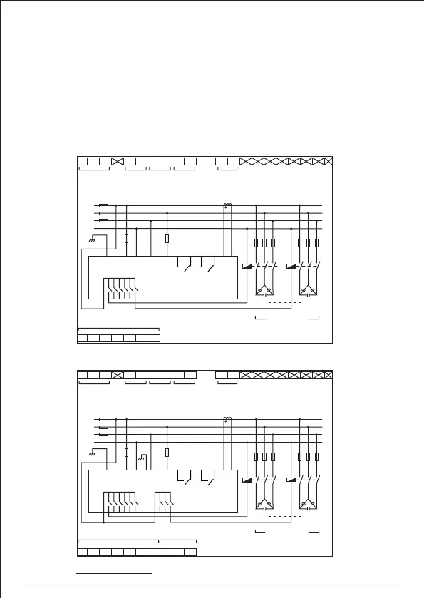
• The current transformer (CT) to be installed at a point where all of the load currents to be
corrected plus the capacitor current are passing. The CT must be installed in any one of the
three phases (Refer Connection Scheme).
• The device must be connected to a power supply circuit and capacitor bank connections
protected with fuse of suitable rating.
• Make sure that correct discharge resistors are fitted to capacitor bank terminals for safety
reason. They are required for discharging capacitor voltage.
1
2
103 65
7
8 9
11
12
21 22
23
24
25 26
27
AUX. SUPPLY
P N E
Capacitor Bank
COM
K1 K2 K3 K4 K5 K6
FAN
RELAY
ALARM
RELAY
CT INPUT
VOLTAGE
Capacitor Bank
11
12
L1
L2
L3
N
21
5 6
7
AUX
SUPPLY
8
22
23
24 26
25 27
9 10
Vin
~
C1
K1 K6
L
O
A
D
C6
1
2
EXT. CT
CSPF-100
CSPF-100
1
2
103 65
7
8 9
11
12
21 22
3023
24
25 26
27
28 29
AUX. SUPPLY
P N E
COM COM
K1 K2 K3 K4 K5 K6 K7 K8
FAN
RELAY
ALARM
RELAY
CT INPUT
VOLTAGE
Capacitor Bank
11
12
L1
L2
L3
N
21 28
53 6
7
AUX
SUPPLY
8
22 29
23
30
24
26
25
27
9 10
Vin
~
C1
K1 K8
L
O
A
D
C8
1
2
EXT. CT
Capacitor Bank Capacitor Bank
CSPF-100-R06-220 : 6 Relay Output contacts for capacitor bank
CSPF-100-R08-220 : 8 Relay Output contacts for capacitor bank
3
3
06