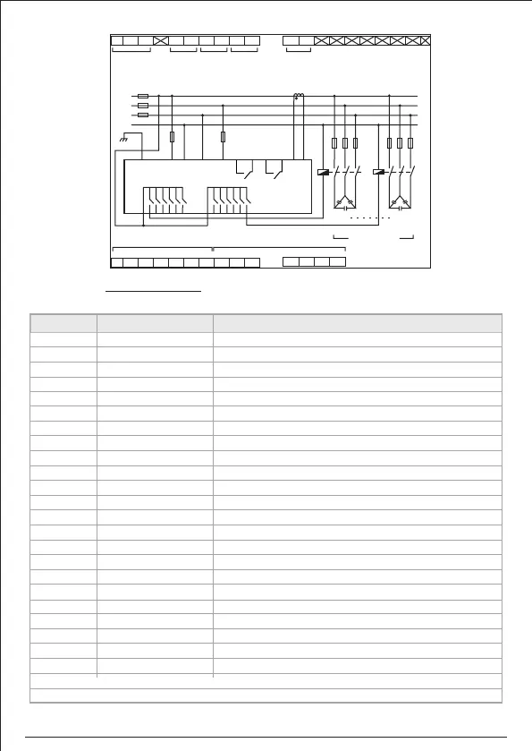
Terminal Description
NOTE: Terminal Nos. not shown are not in use.
Term. No. Connection Name Connection Description
1 Aux Supply (P) Phase for control supply
2 Aux Supply (N) Neutral for control supply
3 Earth
5 Vin Phase Voltage (L3) or (L1)
6 Vin Phase Voltage (L2) or Neutral (N)
7 FAN Output N/O Contact for FAN Relay output
8 FAN Output COM
9 ALARM Output N/O Contact for ALARM Relay output
10 ALARM Output COM
11 Ext CT (S1) External CT Secondary Terminal (In)
12 Ext CT (S2) External CT Secondary Terminal (Out)
21 COMM Common Terminal for Relay contact K1--K6
22 K1 N/O Contact for Cap Bank-1
23 K2 N/O Contact for Cap Bank-2
24 K3 N/O Contact for Cap Bank-3
25 K4 N/O Contact for Cap Bank-4
26 K5 N/O Contact for Cap Bank-5
27 K6 N/O Contact for Cap Bank-6
28 COMM Common Terminal for Relay contact K7--K12
29 K7 N/O Contact for Cap Bank-7
30 K8 N/O Contact for Cap Bank-8
31 K9 N/O Contact for Cap Bank-9
32 K10 N/O Contact for Cap Bank-10
33 K11 N/O Contact for Cap Bank-11
34 K12 N/O Contact for Cap Bank-12
CSPF-100-R12-220 : 12 Relay Output contacts for capacitor bank
1
2
103 65
7
8 9
11
12
21 22
3023
24
25 26
27
28 29 31 32 33 34
N E
COM COM
K1 K2 K3 K4 K5 K6 K7 K8
FAN
RELAY
ALARM
RELAY
CT INPUT
VOLTAGE
K9 K10 K11 K12
Capacitor Bank
11
12
L1
L2
L3
N
21 28
5 6
AUX
SUPPLY
22 29
23 30
24 3126 33
25 3227 34
Vin
~
C1
K1 K12
L
O
A
D
C12
1
2
EXT.CT
Capacitor Contactors
7
8
9
10
S1 S2
Capacitor Contactors
CSPF-100
L
3
07