Do you have a question about the C&S CSPF-100 and is the answer not in the manual?
Key safety warnings and cautions regarding the use and handling of the device.
Essential safety guidelines for installation, maintenance, storage, and wiring of the device.
Critical warnings about electrical hazards, including power disconnection and terminal safety.
Guidelines for the proper disposal and recycling of the product and its components.
Introduction to the Quick Reference Guide (QRG) for installation and setup.
Details about the CSPF-100 Power Factor Controller and its purpose.
List of major functionalities and capabilities of the CSPF-100 relay.
Common industrial and commercial environments where the CSPF-100 is utilized.
Advantages of using the CSPF-100, including cost savings and efficiency improvements.
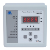
Description of the CSPF-100's front panel layout, indicators, display, and control keys.
Physical dimensions of the CSPF-100 unit in millimeters.
Required dimensions for mounting the CSPF-100 in a control panel.
Diagram of the rear panel showing terminal connections for wiring and installation.
Important safety precautions and guidelines for connecting the CSPF-100 unit.
Wiring schematic for the CSPF-100-R06-220, illustrating 6 relay outputs.
Wiring schematic for the CSPF-100-R08-220, illustrating 8 relay outputs.
Wiring schematic for the CSPF-100-R12-220, illustrating 12 relay outputs.
Detailed explanation of each terminal number and its connection purpose on the CSPF-100.
Configuration options for core parameters like Target Cos Ø, CT Ratio, and delays.
Advanced settings including voltage, phase angle, fan control, and number of banks.
Settings for various alarms like Over Voltage, Over Current, Under Current, and temperature.
Explanation of the HMI screen layout, indicators, and parameter display.
Guide to navigating through the main menu and sub-menu screens for operation and settings.
Step-by-step guide for accessing and editing basic programmable parameters via Sub Menu A1.
Step-by-step guide for accessing and editing advanced programmable parameters via Sub Menu A2.
Procedure for the automatic calculation and setup of the C/k ratio for capacitor banks.
Procedure for testing the relay contacts of the CSPF-100 unit.
Summary of key technical specifications, including voltage, current, and environmental ratings.
Explanation of the C/k ratio and its calculation method for capacitor step selection.
Table providing C/k values based on CT Ratio and Power of 1st Capacitor Step.
Illustrative wiring diagrams for various phase angle settings and connections.
Important note regarding setting the Phase Angle parameter based on wiring schemes.
Common issues, their possible causes, and recommended actions for the CSPF-100.
Information for contacting technical support or after-sales service.
The C&S CSPF-100 Power Factor Controller is designed for automatic or manual control of external capacitor banks in 3-phase, 3-wire, or 4-wire LT distribution systems. Its primary function is to stabilize the power factor of an installation to a desired value, thereby optimizing electrical efficiency.
The CSPF-100 operates by monitoring the power factor of the electrical system and engaging or disengaging capacitor banks as needed to maintain the target power factor. It features a sophisticated control algorithm that ensures effective power factor correction, preventing both over and under-compensation. The device continuously measures and displays various line parameters, including voltage (V), current (I), active power (P), reactive power (Q), apparent power (S), power factor (Cos phi), and temperature. This comprehensive monitoring allows users to gain a detailed understanding of their system's electrical performance.
A key feature is its ability to control up to 12 capacitor banks, offering flexibility for various system sizes and requirements. The controller supports different wiring schemes, making it adaptable to a wide range of installations. It also incorporates a FAN control output and an over-temperature alarm, which are activated based on a built-in temperature sensor, ensuring the longevity and safe operation of the capacitor banks.
The device includes protection and indication features for abnormal conditions such as over/under compensation, over voltage, and over/under current. These alarms alert users to potential issues, allowing for timely intervention and preventing damage to the system. A potential-free alarm output is also available for integration with external alarm systems.
For initial setup and ongoing optimization, the CSPF-100 offers an automatic C/K set-up mode. This mode simplifies the configuration process by automatically calculating the C/K ratio, which is crucial for accurate capacitor bank switching. The C/K ratio represents the power of the first capacitor in kVAr divided by the current transformer ratio. This threshold value determines when capacitor steps are switched on or off.
The user interface of the CSPF-100 is designed for ease of use, featuring a seven-segment display for clear readouts and four keys for navigation, viewing, editing, and saving programmable parameters. LEDs provide additional indications for status and active capacitor banks.
The controller supports both "Auto" and "Manual" operation modes. In "Auto" mode, capacitor steps are connected and disconnected automatically based on the system's power factor requirements. In "Manual" mode, users have direct control over connecting and disconnecting capacitor steps using the UP and DOWN keys, providing flexibility for specific operational needs or troubleshooting.
Programmable parameters are categorized into "Basic Setting" and "Advance Setting." Basic settings include target Cos phi, C/K ratio, external CT ratio, bank switch ON delay, and switching program selection. The switching program determines the kVAr ratio sequence of the connected capacitor bank steps, offering various combinations (e.g., 1:1:1:1:1, 1:2:2:2:2, 1:2:4:4:4, etc.) to suit different load profiles.
Advance settings cover parameters such as nominal voltage, phase angle, bank switch OFF delay, number of capacitor banks used, and fan ON/OFF temperatures. Alarm parameters, including settings for over voltage, over current, under current, over compensation, under compensation, and high/low temperature, are also configurable. These alarm settings can trigger a capacitor bank trip, switching off the banks to protect them from fault conditions.
A field-accessible test mode allows for relay contact checks, ensuring the proper functioning of the switching mechanism. This feature is particularly useful during installation and maintenance. The device also provides a "Return to Prev Menu" and "Return to Main Menu" function, simplifying navigation through the menu structure.
The CSPF-100 is suitable for various applications, including the main incomers of electrical plants, fixed power factor correction for individual loads (such as motors and transformers), and in modern facilities like hi-tech software parks, buildings, and shopping malls. Its robust design and comprehensive features contribute to significant benefits, including savings in installation costs of conductors, reduced electric utility bills, increased system capacity, and a reduction in power losses.
Maintenance of the CSPF-100 is facilitated by its diagnostic capabilities and user-friendly interface. The device's protection and indication features for abnormal conditions serve as early warnings, allowing maintenance personnel to identify and address issues proactively. For instance, an "Over Temperature" alarm, coupled with the FAN control output, helps manage the thermal environment of the capacitor banks, extending their lifespan.
The "Relay Contact Test" mode is a crucial maintenance feature, enabling technicians to verify the functionality of the relay contacts in a sequence. This test helps ensure that the capacitor banks are switching correctly and reliably. The manual mode of operation also provides a means for maintenance personnel to test individual capacitor steps and troubleshoot the system without relying on automatic control.
The Quick Reference Guide (QRG) emphasizes the importance of following safety procedures during installation, maintenance, and inspection, recommending that these tasks be performed by qualified staff. It also provides troubleshooting points for common issues, such as "Display Not Visible," "Wrong measurement of voltage/current/power factor," and "No capacitor steps are switching though present load is inductive." Each troubleshooting point includes possible causes and recommended actions, guiding maintenance personnel through diagnostic steps. For example, if the power factor measurement is wrong, the guide suggests checking CT polarity, phase angle settings, and wiring connections.
Proper storage conditions are also outlined, recommending a dry location with a temperature between -10°C and +70°C if the system is not immediately put into service. This helps preserve the device's integrity before installation. The guide also highlights the importance of checking for delivery damage and ensuring the correct model has been supplied.
The CSPF-100's design, with its clear display of line parameters and alarm conditions, allows for continuous monitoring of system health. This proactive approach to maintenance, combined with the device's diagnostic tools and clear operational guidelines, helps ensure reliable and efficient power factor correction over time.
| Input Voltage | 100-240VAC |
|---|---|
| Output Voltage | 12VDC |
| Output Current | 8.5A |
| Power | 100W |
| Protection | Short Circuit |