21
The operations must be executed by a qualified technician.
IMPORTANT
All intervention regarding installation maintenance and conversion of the
appliance must be fulfilled with original factory parts.
The manufacturer declines any liability resulting from the non-compliance of
this obligation.
Lubrication of the gas taps
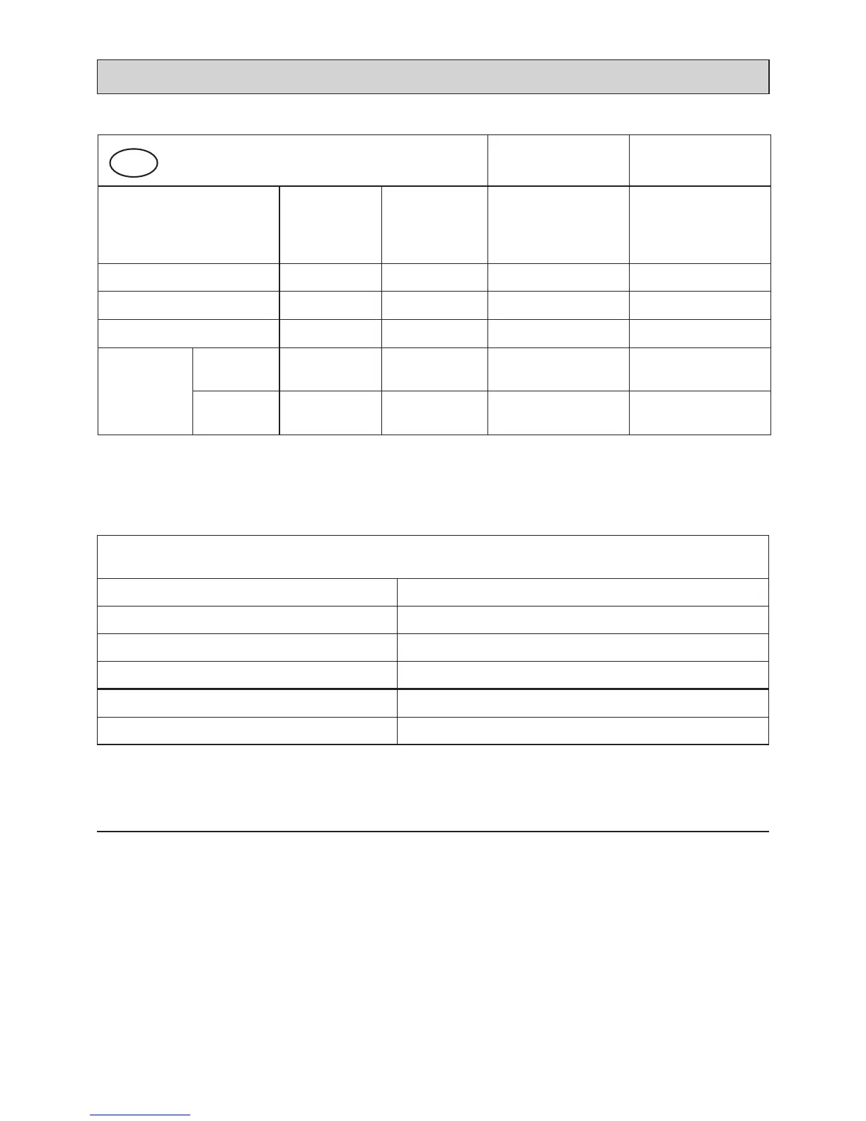
TABLE FOR THE CHOICE OF THE INJECTORS
Cat: II 2H 3+
G30/G31
28-30/37 mbar
G 20
20 mbar
BURNERS
Nominal
Power
[Hs - kW]
Reduced
Power
[Hs - kW]
Ø injector
[1/100 mm]
Ø injector
[1/100 mm]
Auxiliary (A) 1,00 0,30 50 72 (X)
Semi-rapid (SR) 1,75 0,45 65 97 (Z)
Triple ring (TR) 3,50 1,50 95 135 (T)
Dual (DB)
inner crown
1,00 (#) 0,32 (#)
50
(no. 1 central)
69 (F1)
(no. 1 central)
outer crowns
4,50 (*) 1,90 (*)
66
(no. 2 outer)
102 (Z)
(no. 2 outer)
(#): Power calculated with inner crown operating.
(
*
): Power calculated with inner and outer crowns operating.
Air vent necessAry for gAs combustion
= (2 m
3
/h x kW)
BURNERS Air necessary for combustion [m
3
/h]
Auxiliary (A) 2,00
Semi-rapid (SR) 3,50
Triple ring (TR) 7,00
Dual (DB) -
inner crown operating 2,00
Dual (DB) -
inner & outer crowns operating 9,00
 Loading...