7
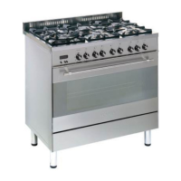
Electrical feeder cable
connection
To connect the feeder cable to the cooker
it is necessary to:
– Remove the screw that hold shield “A”
behind the cooker (fig. 1.2).
– Insert the feeder cable of the suitable
section (as described in the next
chapter) into the cable clamp “D”.
– Connect the phase and earth cables
to the terminal block “B” according to
the diagram in figure 1.3.
– Pull the feeder cable and block it with
cable clamp “D”.
– Re-mount shield “A”.
N.B. The earth conductor must be left
about 3 cm longer than the others.
Fig. 1.2
D
B
A
230 V
PEN
L
1
(L2)
Fig. 1.3
PE
Electrical Installation - Wall box connection
FEEDER CABLE SECTION
type H05RR-F
230 V 3 x 2,5 mm
2
(**)
(**) – Connection with wall box connection.
PE Earth
N Neutral
L Live
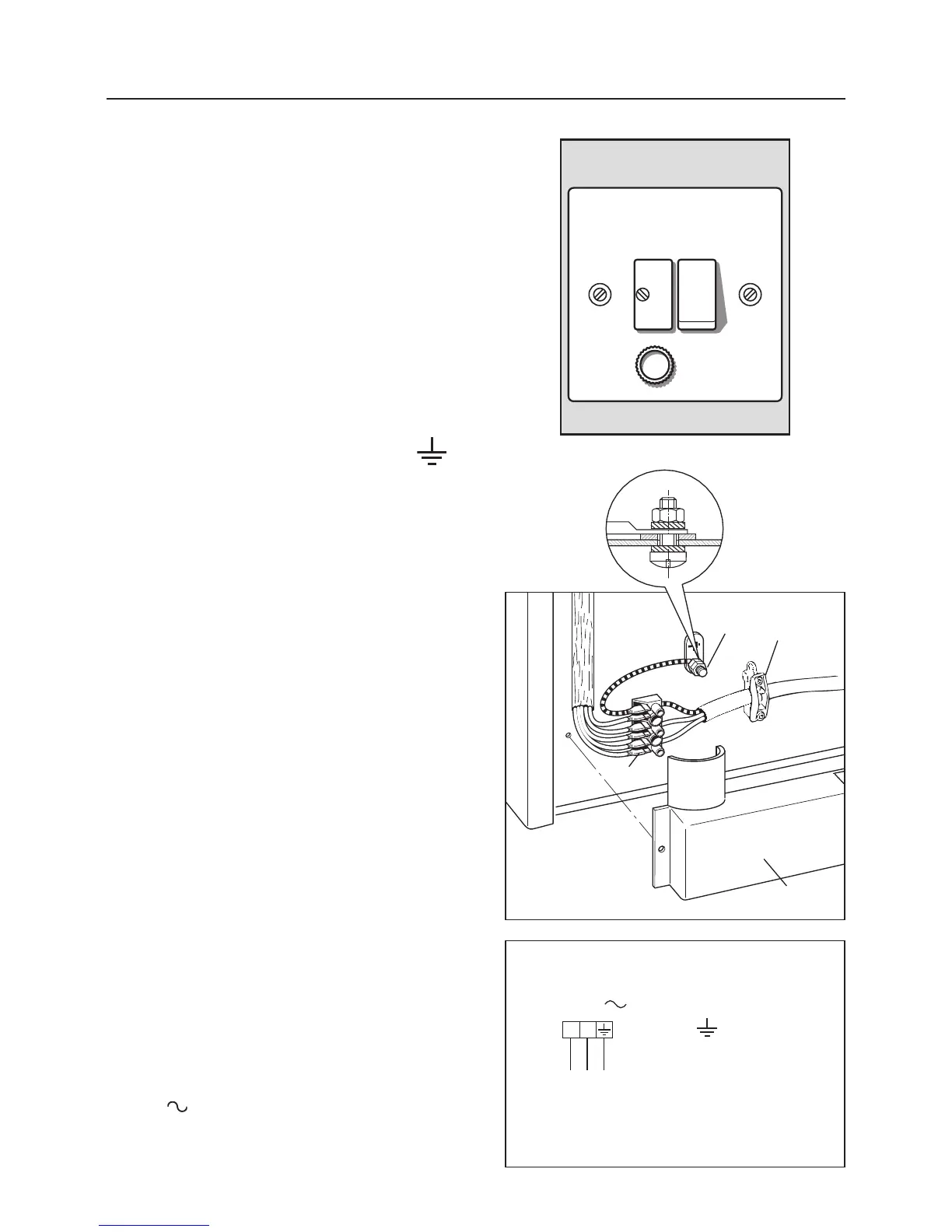
This appliance must be connected to a
double pole isolating switch (fig. 1.1) and
to the terminal block in the cooker (figs.
1.2, & 1.3) using the following guide:
FUSE
DOUBLE POLE SWITCHED
FUSED SPUR OUTLET
USE A 20 AMP FUSE
ON
Fig. 1.1
1) The wire which is coloured brown
must be connected to the terminal
marked L (Live), or coloured Red.
2) The wire which is coloured blue must
be connected to the terminal marked
N (Neutral), or coloured Black.
3) The wire which is coloured green
and yellow must be connected to
the terminal marked E (Earth)
or coloured Green.
IMPORTANT: These connections must
be carried out by a qualified electrical
engineer.