50 docs.carbide3d.com support@carbide3d.com 51
Next Steps
1. Connect to Power
2.
3. Carbide Motion 5
Connect to Power
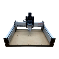
Required Components
See Figure10‑1:
Item Description Qty
A Power Supply 1
B Power Cord 1
1. Connect the power cord to the power supply.
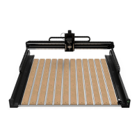
2. Connect the power supply to the power port
on the rear of the Carbide Motion board as
shown in Figure10‑2.
3.
the power supply will light up when connected
to power. See Figure10‑2.
4. Flip the in-line rocker switch on the power
Figure10‑2.
Download the Software
1. carbide3d.com/carbidemotion/download.
2. carbide3d.com/carbidecreate.
3. Install both programs to your computer.
Carbide Motion lets you control your machine by jogging it around, setting zeros, and running G-code.
implement your design.
Congure Carbide Motion 5
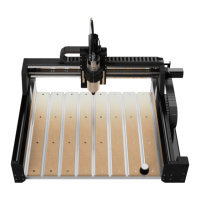
Required Components
See Figure11‑1:
Item Description Qty
A USB Cable 1
Connect to Carbide Motion 5
1. Turn your computer on.
2. Connect the USB cable to your Carbide Motion
board and to your computer.
3. Start Carbide Motion 5 on your computer.
4. Flip the in-line rocker switch on the power
Shapeoko 3.
5. In Carbide Motion, click the Connect to Cutter
button.
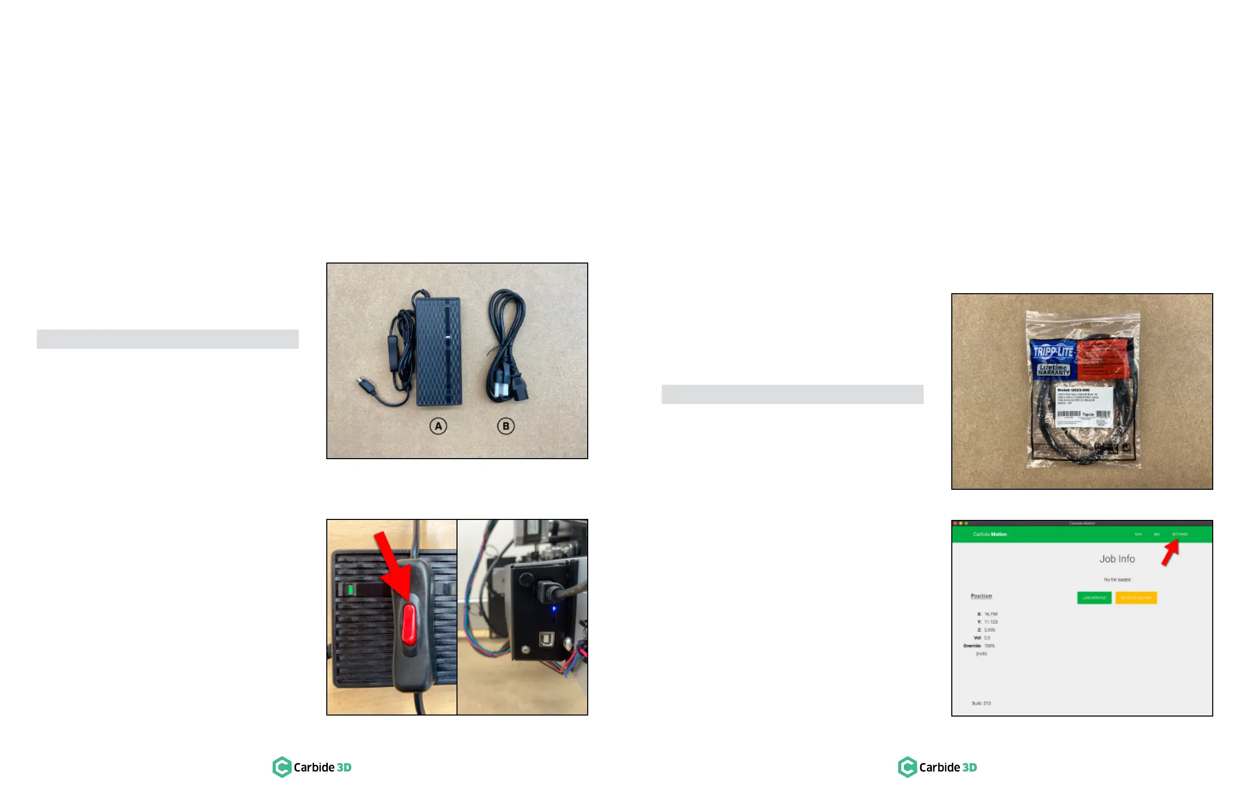
Upload Your Settings
1.
Settings button in the top menu bar to open
the Settings menu. See Figure11‑2.
4. Run the Test Project
5. Workholding
Cutting Tutorials & Projects
7. User Guides & Video Tutorials
8. Glossary of Terms
Machine-Use Log
Figure10-1
Figure11-1
Figure11-2
Figure10-2
 Loading...