docs.carbide3d.com support@carbide3d.com 27
Insert the Y1-Rail
1. Slide the V-rails of the Y1-rail between the four
rail between the front and rear endplates. See
Figure4‑5.
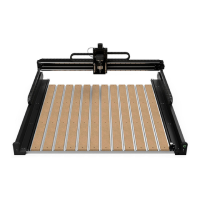
Insert the Y2-Rail
1. Slide the V-rails of the Y2-rail between the four
rail between the front and rear endplates. See
Figure4‑6.
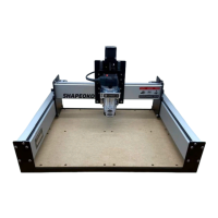
Secure the Gantry
Position the Gantry
1. Lift the gantry and place it onto the baseframe
with the Y1- and Y2-rails positioned between
the front and rear endplates. Use caution,
forward. See Figure4‑7.
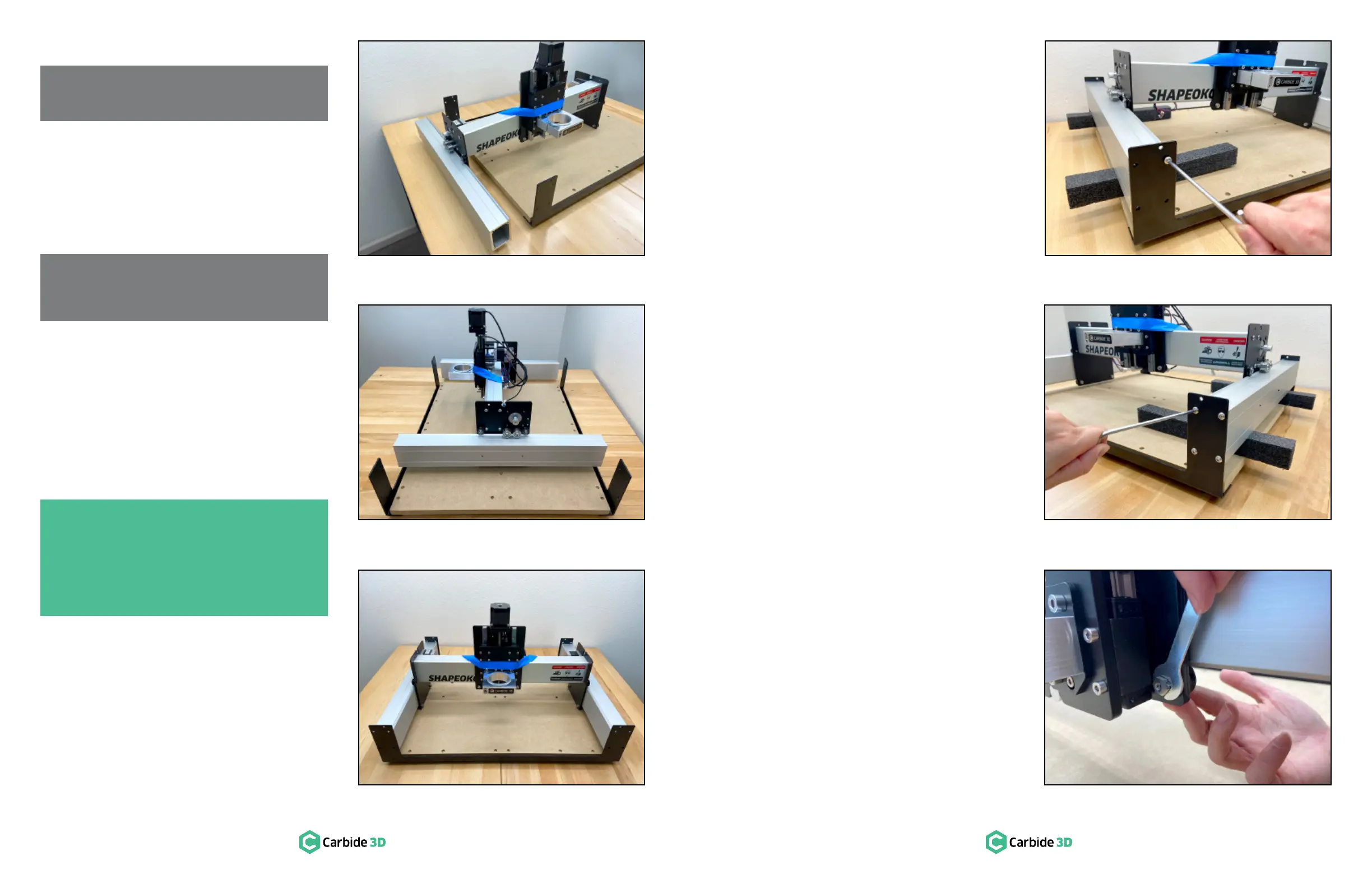
Secure the Y1-Rail
The Y1- and Y2-rails will be raised into place one
loosely attached to the endplates with two screws,
for rotating the Y2-rail up and into place.
1. Prop up the Y1-rail with the two long foam
packing blocks from the X/Z+ box. See
Figure4‑8.
2. Align the UPPER-INSIDE screw holes of the
Y1-rail with the same through-holes of the
FRONT and REAR endplates. See Figure4‑8.
3. ×12mm
button head cap screws to loosely attach the
Y1-rail to the UPPER-INSIDE holes in the front
and rear endplates. See Figure4‑8.
into place.
Secure the Y2-Rail
1.
Y1-rail and use them to prop up the Y2-rail.
2. ×12mm
button head cap screws to secure the
Y2-rail to the front and rear endplates. See
Figure4‑9.
Complete Rail Assembly
1.
×12mm button head cap screws to secure
the Y1-rail to the front and rear endplates.
2.
between the rails and endplates, but do not
fully tighten.
Tension the V‑Wheels
1.
the V-wheels engage with the V-rails. See
Figure4‑10.
Refer back to the eccentric nut information on page
18 and Figures 3‑4 and 3‑5, if needed.
NOTE: The Y1-rail is plain, there are no
threaded holes on either side of the rail.
PRO TIP: The gantry can be awkward to
handle alone. Enlist the help of another
person when lifting and positioning it. Each
person should use one hand to lift the gantry
by the X-rail and the other hand to center the
Y-rails between the endplates.
NOTE: The Y2-rail has two M6 threaded
screw holes on one side. The holes are for
mounting the optional BitRunner accessory.
Figure4-5
Figure4-6
Figure4-7
Figure4-8
Figure4-9
Figure4-10
 Loading...