24 docs.carbide3d.com support@carbide3d.com 25
Required Components
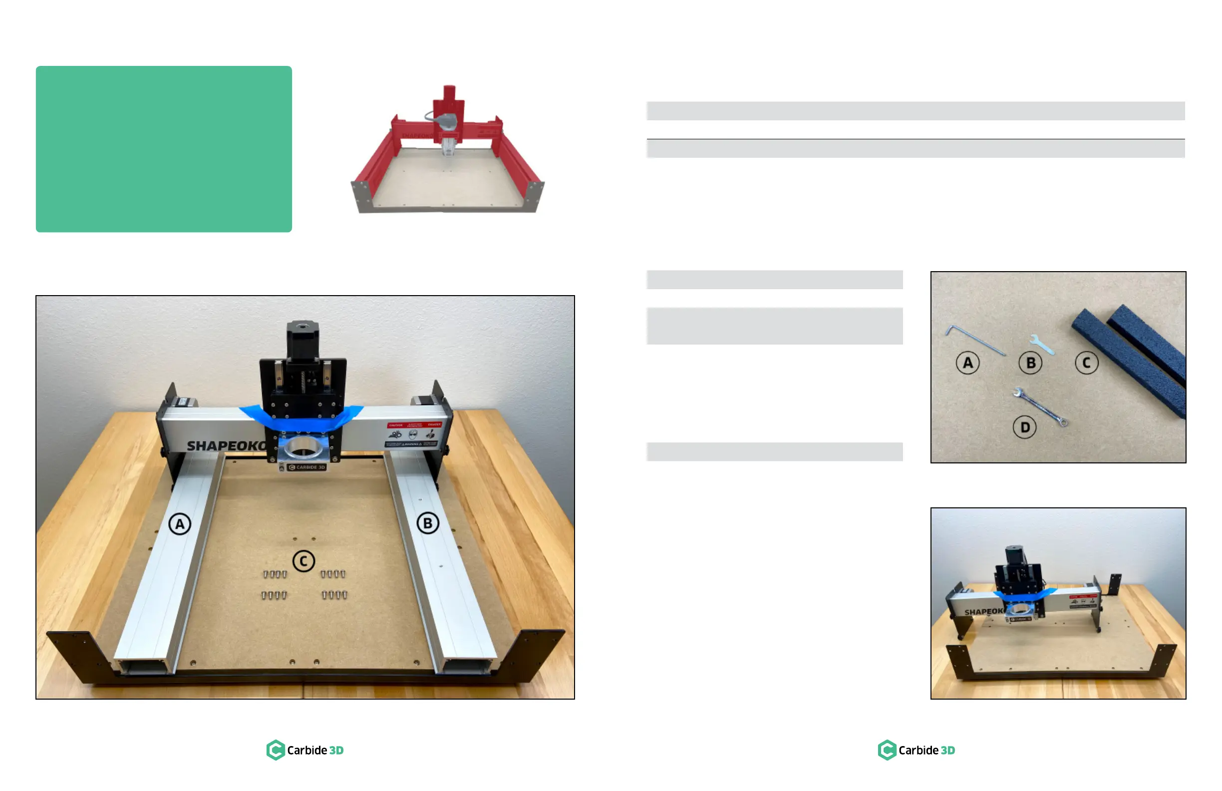
See Figure4‑2:
Item Description Location Qty
A Y-Axis Left Aluminum Extrusion Rail (Y1-Rail) N/A 1
C × 12mm Button Head Cap Screw Shapeoko 3 Final Assembly Box 8
B Y-Axis Right Aluminum Extrusion Rail (Y2-Rail) N/A 1
C × 12mm Button Head Cap Screw Shapeoko 3 Final Assembly Box 8
Required Tools
See Figure4‑3:
Item Description Qty
A 4mm Hex Key 1
B 10mm Wrench 1
C
Foam Packing Block (From the
2
Recommended Tools
See Figure4‑3:
Item Description Qty
D 10mm Combination Wrench 1
Assemble the Gantry
In this step, we’ll be inserting the Y1- and Y2-rails
into the carriages and securing them to the
baseframe to form the gantry.
Position the X-Rail
1. Place the X-rail/carriage assembly across the
middle of the baseframe, shifted slightly to
the left, with the Y1-carriage on the tabletop
and the Y2-carriage on the baseplate. See
Figure4‑4.
Figure4-2
Figure4-3
Figure4-4
Step 4
Gantry
 Loading...