41
OPTICALLY ISOLATED INPUTS
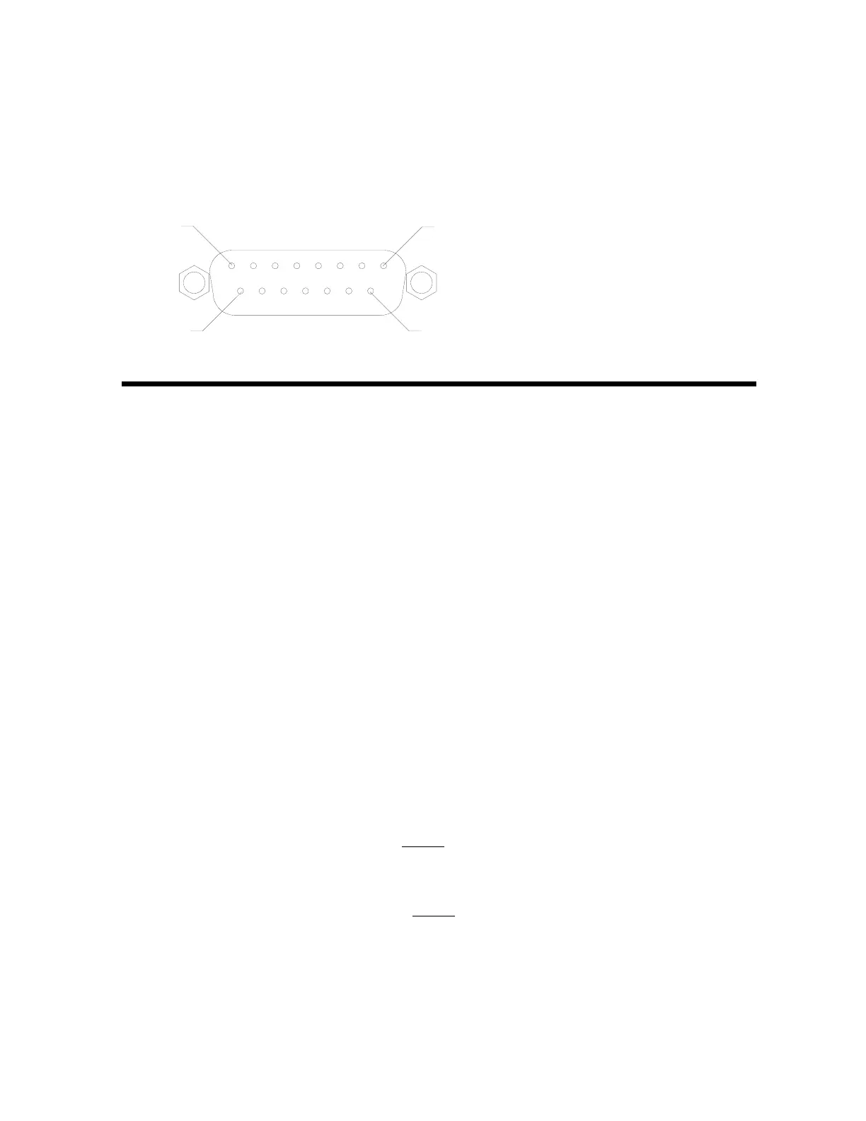
Included with the I/O option are eight (8) programmable inputs that may be used to remotely (up to
100 feet) initiate various functions within the 748. These inputs are accessed via the 15-pin “D”
series connector on the back of the instrument enclosure. Four (4) of the inputs are defined while
the remaining four (4) are available for special applications and will vary from application to
application. Of the four (4) that are defined, one is for Zero, another is for Tare, the third is for Print,
and the fourth is for Gross. Figure no. 16 illustrates the layout of this connector and identifies the
inputs for Zero, Tare, Print and Gross. Remember that the input must be connected to Gnd to initiate
the function.
PIN NUMBER FUNCTION
1 .................... Zero
9 .................... Tare
2 .................... Print
10 .................. Gross
3
11
4
12
5 .....................Gnd
13 ....................Gnd
CALIBRATION OF THE ANALOG OUTPUT
The analog output has been calibrated at the factory and should require no other adjustment. If, for
some reason, it is found necessary or desirable to readjust this output, the procedure listed below
may be used. Note that in order to calibrate the analog output, it is first necessary to enter the
Calibration mode by gaining access to the calibration switch. Refer to the CALIBRATION section of
this manual for additional information. When the 748 senses that the optional I/O board is present, it
will cause the calibration sequence to include the steps necessary to calibrate the analog output.
The following describes that process:
Step 1 The display will show CALdAC.
Step 2 Press the ENTER key and the display will show NO. If you press ENTER at this point, the
analog output calibration process will be ended. Press the 1 key to change the display
to YES to proceed with Step 3 of the analog output calibration, or press the 0 key to
change the display back to no. Press ENTER.
Step 3 The display will show bH 0=, the weight below zero for the analog output to be minimum
(0 volts or 4 MA). Press ENTER to display the displayed setting. Press ENTER to store
displayed setting, or enter the desired weight and press ENTER.
Step 4 The display will show dAC H=, the maximum voltage to be output at capacity. Press
ENTER to display the displayed setting. Press ENTER to store the displayed setting or
enter the desired value 00.000 to 10.000 and press ENTER.
If the maximum voltage is known, the current output will be:
Current = x 16 + 4 (mA)
If the maximum current is known, the dAC H= setting will be:
dAC H= x 10 (volts)
00.000 = 4.0mA
5.000 = 12.0mA
10.000 = 20.0mA
()
setting
10
PIN 1
PIN 8
PIN 15
PIN 9
figure no. 16 - logic level connector layout
()
mA - 4
16