8
pGD
1
user interface
EV driver
E
2
V
TP
EV d ri ve r
E
2
V
TP
Master control
Supervisor (CAREL o Modbus)
Fig. 1.1
Fig. 1.2
Fig. 1.3
pGD
1
user interface
EV driver
E
2
V
TP
ENGLISH
EVD
4
+030220227 - rel. 2.1 - 12.06.2008
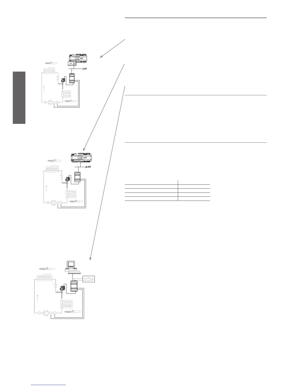
1.2 Connecting to the main serial port
EVD
4
can operate independently (stand alone), connected to a supervisor to control the fundamental
parameters, or connected to the LAN with other CAREL controllers, according to the following diagrams:
1.2.1 TLAN connection with µC2 or µC2 SE or pCO (codes EVD000*40* and EVD000*43*)
Fig. 1.1.
1.2.2 pLAN connection with pCO (codes EVD000*41* and EVD000*44*)
Fig. 1.2.
1.2.3 Stand alone in the RS485 network with CAREL supervisor (codes EVD000*42* and
EVD000*45*) or with Modbus® supervisor (code EVD0001460)
Fig. 1.3.
1.3 Operation of the service serial port
The service serial port (par. 2.5) is used to access all the EVD4 parameters even when the instrument is
already installed and operating; to do this, the special converter is required (CVSTDUTTL0 or CVSTD0TTL0),
plus a PC with USB or RS232 serial port. “APPENDIX I - Installing and using the EVD4-UI program” describes
the installation and operation of the EVD4_UI software that is used to confi gure the controller.
The converter can power the logical section of the EVD4 (but not the expansion valve), and therefore this
can be confi gured from the PC without having to connect the instrument to the 24 Vac power supply.
1.4 Setting the network address
The EVD
4
operating parameters, including the network address, reside on the EEPROM; to modify the va-
lues, access the service serial port using the EVD4-UI software: connect the special converter (CVSTDUTTL0
or CVSTD0TTL0) to the service serial port (Fig. 2.8) and a PC with USB or RS232 serial port, then start the
“EVD4_U Key” connection, as described in “APPENDIX I - Installing and using the EVD4-UI Address” and set
the Net address parameter; in the box at the top right of the interface, the “Network address” item will show
the new value of the address, after having pressed the “READ” button. If not changed by the user, the Net
address parameter will have the following default values:
Net address
EVD000*40* and EVD000*43* 2
EVD000*41* and EVD000*44* 30
EVD000*42* and EVD000*45* 32
EVD0001460 1
Below is a description of the connectors supplied with the EVD000*4*0 or purchased in separately in
the EVDCON0001 kit for EVD000*4*1. The drawings represent the connectors as seen after having been
fi tted on the EVD
4
.
Note: if the address is changed using the pLAN or Modbus
®, protocol, the “Network address” item is
updated after switching the device off and on again.