30
G Vbat DI1 S4V S3 S2 S1
G0 GND DI2 S4I Vr1 Vr2 OC
NTC -50T105 °C
S3
Temperature
NTC*WF*
Digital input
DI1
GND
GNDDI1
ratiometric +
OUT
Vr1
Ratiometric
pressure SPKT*R*
GND
P
S1
MOLEX
®
Mini-Fit 538-39-01-2140
G Vbat DI1 S4V S3 S2 S1
G0 GND DI2 S4I Vr1 Vr2 OC
NTC 0T150 °C
S2
NTC*HT*
GND GND
PT1000
S2
TSQ*
NTC -50T105 °C
S1
NTC*WF*
GND
DI2
DI1 GND GND
4…20 mA
S4I
0…10 V
S4V
+
GND
10 mA max
10 Vdc max
OC
+
GND
GNDDI2
or
Vr2 S2
S3
or
ratiometric +
OUT
SPKT*R*
GND
P
Fig. 4.1
Fig. 4.2
ENGLISH
EVD
4
+030220227 - rel. 2.1 - 12.06.2008
4. TECHNICAL AND CONSTRUCTIONAL SPECIFICATIONS
Installation and storage specifi cations
Operating conditions -10T60°C, < 90% RH non-condensing
Storage conditions -20T70°C, < 90% RH non-condensing
Index of protection IP20
Wire cross-section 0.5 to 2.5 mm
2
Dimensions 70 x 110 x 60
PTI of insulating materials 250 V
Protection against electric shock to be integrated into class I and/or II equipment
Degree of environmental pollution normal
Resistance to heat and fi re category D
Immunity against voltage surges category 1
Surface temperature limits as per the operating conditions
Assembly on DIN rail
Case width 4 modules
Disposal
the module is made up of metal and plastic parts. These must be
disposed of according to the waste disposal local legislation in force
Motor control
The controller works with two-pole stepper motors (Fig. 1). It works with a theoretical sinusoidal wave-
form, in micro-steps and with speeds from 5 to 1000 steps; the current and the control speed effectively
achievable depend on the resistance and the inductance of the motor windings used. If the driver is
connected to a pCO, it receives all the individual operating parameters for the motor from the pCO
controller, if, on the other hand, it is used in stand-alone mode or with the microchiller controller, only
one parameter needs to be set, taken from Table 5, according to the model of motor used (see Table 5).
The controller can manage motors with maximum positions of up to 32000 steps. For connection use
4-wire shielded cables, AWG18/22, max. length 9.5 m. The shield should be connected to the closest
possible earth point in the panel.
Power supply
Power supply: 20 to 28 Vac or 20 to 30 Vdc 50/60 Hz to be protected by external 0.8 A fuse, type T.
Use a class II safety transformer rated to at least 20 VA. Average current input at 24 Vac: 60 mA with the
motor not operating (control logic only); 240 mA with CAREL motor operating (240 mA peak at 18 Ω).
Emergency power supply: if the optional EVBAT00200/300 module is installed, power supply is
guaranteed to the controller for the time required to close the valve.
Inputs and outputs
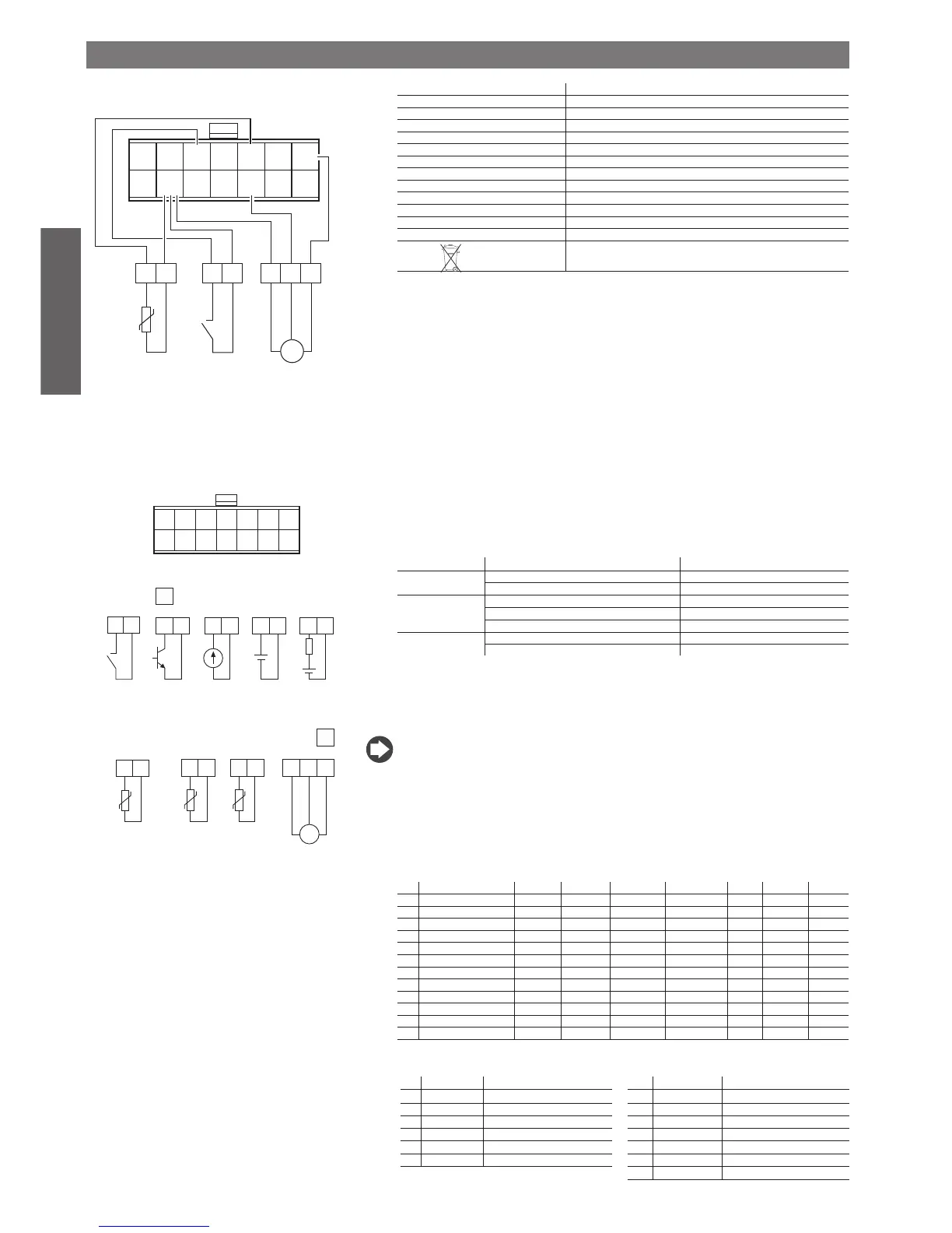
Analogue inputs (*)
input type CAREL code
S1-S3: NTC (-50T105 °C) NTC*WF*
Raziom. (0,5…4,5 Vdc) SPKT*R*
S2: NTC (0T150 °C) NTC*HT*
Raziom. (0,5…4,5 Vdc) SPKT*R*
Pt1000 TSQ*
S4: current at 100 Ω 4…20 mA
voltage at 1 kΩ 0…10 V
Digital inputs ID1 and ID2: controlled by voltage-free contact or transistor, have a no-load voltage of 5 V and
deliver 5 mA short-circuited.
Digital output OC: open-collector transistor; max no-load voltage 10 V, max current 10 mA.
Relay output: normally open contact; 5 A 250 Vac resistive load; 2 A 250 Vac, inductive load (PF= 0.4).
(*) WARNING! All analogue inputs except for S4 V, the digital I/O and the serial port (not optically-
isolated) refer to the GND earth, (Fig. 3) and consequently the even temporary application of voltages
higher than ±5 V to these connectors may cause irreversible damage to the controller. Input S4 V can
tolerate voltages up to 30 V. As GND is the common earth for all the inputs, this should be replicated
on the terminal block with low-resistance connections for each input used. The GNX earth for the serial
connection is electrically connected to the GND earth. The product complies with Directive 89/336/EEC
(EMC). Contact CAREL if specifi c disturbance occurs in the confi guration used. If the connection to the
motor is made using a shielded cable, the cable shield and the channel marked by the earth symbol on
the 6-pin connector must be earthed as near as possible to the EVD400.
Valve table
n° Model Step min Step max Step close Step/s speed mA pk mA hold % duty
0 CAREL E2V* 50 480 500 100 450 100 30
1 Sporlan SEI 0.5-20 100 1596 3600 200 200 50 70
2 Sporlan SEI 30 200 3193 3600 200 200 50 70
3 Sporlan SEH 50-250 400 6386 7500 200 200 50 70
4 Alco EX5-EX6 100 750 750 450 400 100 70
5 Alco EX7 250 1600 1600 330 750 250 70
6 Alco EX8 330 step/s 250 2600 2600 330 800 500 70
7 Alco EX8 500 step/s 250 2600 2600 500 800 500 70
8 Danfoss ETS-25/50 200 2625 2700 120 140 75 70
9 Danfoss ETS-100 300 3530 3600 120 140 75 70
10 CAREL E2V*P 50 380 400 100 450 100 30
11 Danfoss ETS-250/400 350 3810 3900 120 140 75 70
Table of refrigerants (consult the electronic expansion valve technical documentation to check
the complete valve-driver system compatibility with the chosen refrigerant)
n° “R” number operating temperature n° “R” number operating temperature
1 R22 -40T60 7 R290 -50T96
2 R134a -40T60 8 R600 -50T90
3 R404a -40T60 9 R600a -50T90
4 R407c -40T60 10 R717 -60T70
5 R410a -40T60 11 R744 -50T31
6 R507c -40T60 12 R728 -201T-145
13 R1270 -60T90
Probe connections (Default)
Other connections