7
ENG
+0300046IE - rel. 1.2 - 14.01.2021
1. PRODUCT DESCRIPTIONS
1.1 Intended Uses / Applications
The GLD series detector instruments continuously monitor ambient air
(indoor or outdoor) to detect any refrigerant leakage.
These devices can be used for refrigeration applications (cold-rooms,
freezer rooms, plantrooms).
The GLD series detectors are available in the following configurations:
• GDWB – Built-In version
• GDWR – Remote version
and these are calibrated to detect most refrigerants currently on the
market.
Sensible elements are built using semiconductor technology (SC) or
infrared technology (IR).
Both the versions are provided with screws for wall mounting and a
magnetic wand.
An RJ45 cable is also provided for Remote version.
The GLD series detectors can be used in stand-alone applications, or
integrated with Carel controllers or third party devices.
Connection to Carel controllers is made using an analogue or digital
output or Modbus® RS485 serial connection.
When a refrigerant leak exceeding a certain alarm concentration is
detected, the device enters in alarm status (low or high, depending on
exceeded concentration level):
• changing internal LED colour and blinking frequency;
• activating internal buzzer;
• activating a dedicated internal relay (SPDT);
• regulating the analogue output (proportional to detected
concentration);
• reporting the state change through Modbus® RS485 output and the
app RILEVA.
Furthermore, it is possible to connect to the device through the app
“RILEVA”, available on both App Store and Play Store.
The GLD series detector allows compliance with refrigeration safety
standards (ASHRAE 15 and EN 378), by featuring audible and visual alarms
to alert personnel in the event of a refrigerant leak.
WARNING: This instrument is neither certified nor approved for
operation in oxygen-enriched atmospheres. Failure to comply
may result in EXPLOSION.
WARNING: this device has not been designed to guarantee
intrinsic safety when used in areas classified as hazardous (“Direc-
tive 2014/34/EU ATEX” and “NFPA 70, Hazardous Location”). For
operator safety, DO NOT use it in hazardous locations (classified
as such).
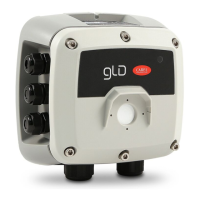
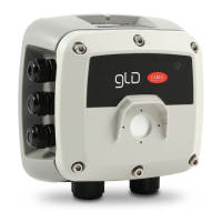
1.2 Gas Leakage Detector, Built-In Version
142 mm
168 mm 81 mm
158 mm
Fig. 1.a
Enclosure description: IP66 rated ABS enclosure
Power options 24 Vac
19.5 to 28.5 VDC
Diagnostic/status LED 3 color: green, orange and red)
Configurable output
signal options
3× Relays (high alarm / low alarm / fault)
1× Analog Output (4 to 20 mA, 0 to 5 V,
0 to 10 V, 1 to 5 V, 2 to 10 V)
Digital Output (Modbus RS485)
11
1515
2
MAG #2
MAG #1
8
NO
COM
NC
–
+
–
+
NO
COM
NC
B
A
GND
SH
AN+
GND
NO
COM
NC
6
10
7 9
5
13
14
12
11
3
4
IN
OUT
NO
COM
NC
–
+
–
+
NO
COM
NC
B
A
GND
SH
AN+
GND
NO
COM
NC
6
10
7 9
5
13
14
12
11
3
4
IN
OUT
Fig. 1.b
# Component Description # Component Description
1 M16 Cable Glands (×6) 9 Tactile Switch #2
2 Rubber Gasket 10 Relay 3 Connection (FAULT)
3 Internal Alarm Buzzer 11 Relay 2 Connection (HIGH)
4 Power Connections (×2) 12 Relay 1 Connection (LOW)
5 Digital Connection (Modbus) 13 Magnetic Switch #1
6 Analog Connection 14 Magnetic Switch #2
7 Tactile Switch #1 15 M20 Cable Glands (×2)
8 Ribbon Cable Connection (To Sensor)
Tab. 1.a
– + – +
B
A
GND
SH
AN+
GND
NC
COM
NO
NC
COM
NO
NC
COM
NO
4 5
10 11 12
6
 Loading...