8
ITA
+0300046IE - rel. 1.2 - 14.01.2021
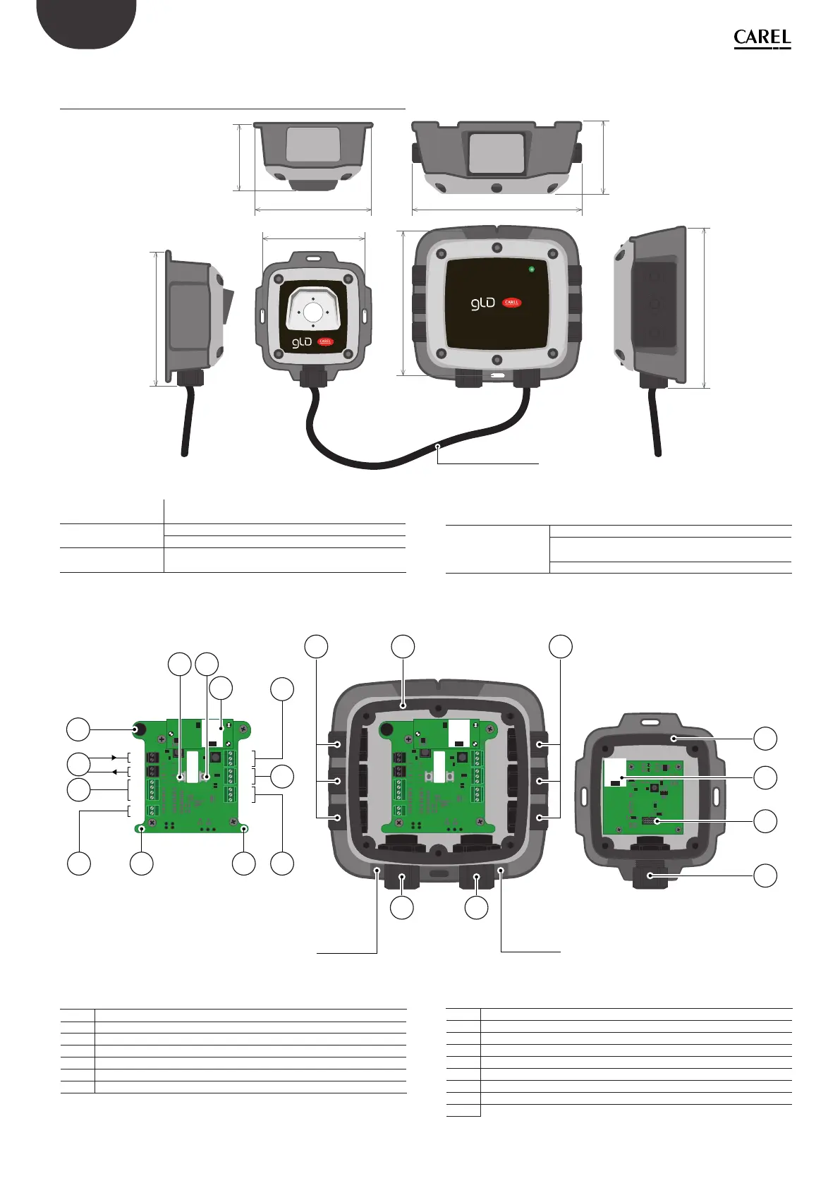
1.3 Rilevatore di perdite di gas, versione
remota
Connection cable
142
102
116 168
136
67
70
159
Fig. 1.c
Descrizione
contenitore:
2 contenitori in ABS con grado di protezione IP66 colle-
gati tramite cavo RJ45 (no a 5 metri di lunghezza)
Opzioni di potenza 24 Vac
da 19,5 a 28,5 V DC
LED di diagnostica/
stato
3 colori: verde, arancione e rosso
Opzioni di segnali di
uscita congurabili
3 relè (allarme alto / allarme basso / anomalia)
1 uscita analogica (da 4 a 20 mA, da 0 a 5 V,
da 0 a 10 V, da 1 a 5 V, da 2 a 10 V)
Uscita digitale (Modbus RS485)
2
8
16
15
11
1515
2
8
MAG #2
REMOTE SENSOR
MAG #1
6
10
7 9
5
13 14
12
11
3
4
IN
OUT
NO
COM
NC
–
+
–
+
NO
COM
NC
B
A
GND
SH
AN+
GND
NO
COM
NC
Fig. 1.d
N° Descrizione componente
1 Pressacavi M16 (6)
2 Guarnizioni in gomma (2)
3 Cicalino allarme interno
4 Connettori di alimentazione (2)
5 Connettore seriale (Modbus)
6 Uscita analogica
7 Interruttore tattile n° 1
N° Descrizione componente
8 Connessioni del sensore remoto (2)
9 Interruttore tattile n° 2
10 Uscita relè 3 (ANOMALIA)
11 Uscita relè 2 (ALTO)
12 Uscita relè 1 (BASSO)
13 Interruttore magnetico n° 1
14 Interruttore magnetico n° 2
15 Pressacavi M20 (3)
16 Connettore cavo piatto (al sensore)
Tab. 1.b
 Loading...