9
B
D
C
A
A
B
D
C
ENGLISH
humiDisk - +030222022 - rel. 2.1 - 01.03.2012
2.1 Material supplied
The following materials are supplied as standard with the appliance. Check that all the material listed below
is included in the packaging before starting work.
For humiDisk
10
• 1 humiDisk
10
model humidifi er;
• 1 technical installation manual (this manual);
• 3 brackets for hanging installation.
For humiDisk
65
The following materials are supplied as standard with the appliance. Check that all the material listed below
is included in the packaging before starting work.
• 1 humiDisk
65
model humidifi er;
• 1 technical installation manual (this manual);
• 4 wall plugs with screws (for wall mounting);
• 1 bracket for wall-mounting;
• 3 brackets for hanging installation;
• 1 M6x20 hexagonal safety screw;
• 1 washer dia. 6x2;
• 1 water supply hose l=1.5 m, with G ¾ threaded fi ttings;
• 1 water drain hose l=1.5 m ID 10;
• 3 wiring clamps.
2.2 Preliminary operations
To make the humiDisk
10
and humiDisk
65
operative, the following are required:
• mains power supply, 230V, 50Hz, with an earth connection and protection devices
• water supply connection
• water drain connection.
Note: Installation must comply with the safety requirements of the local standards in force.
Then make sure that all the necessary connections to make the appliance operate properly have been
correctly prepared.
For the humiDisk
10
all the connections, both electrical and water, are located at the rear, as shown in Fig
2.a. The operations listed below should be completed before starting actual installation. With reference to
Fig. 2.a:
• connect the water drain hose A, not supplied as standard but available on order, code UCKTS00000, to
the drain elbow B;
• connect end C with the elbow of the water supply hose, not supplied as standard but available on order
codeUCKTA00000, to the fi ll solenoid valve D.
The above-mentioned operations can in any case also be carried out with the unit installed.
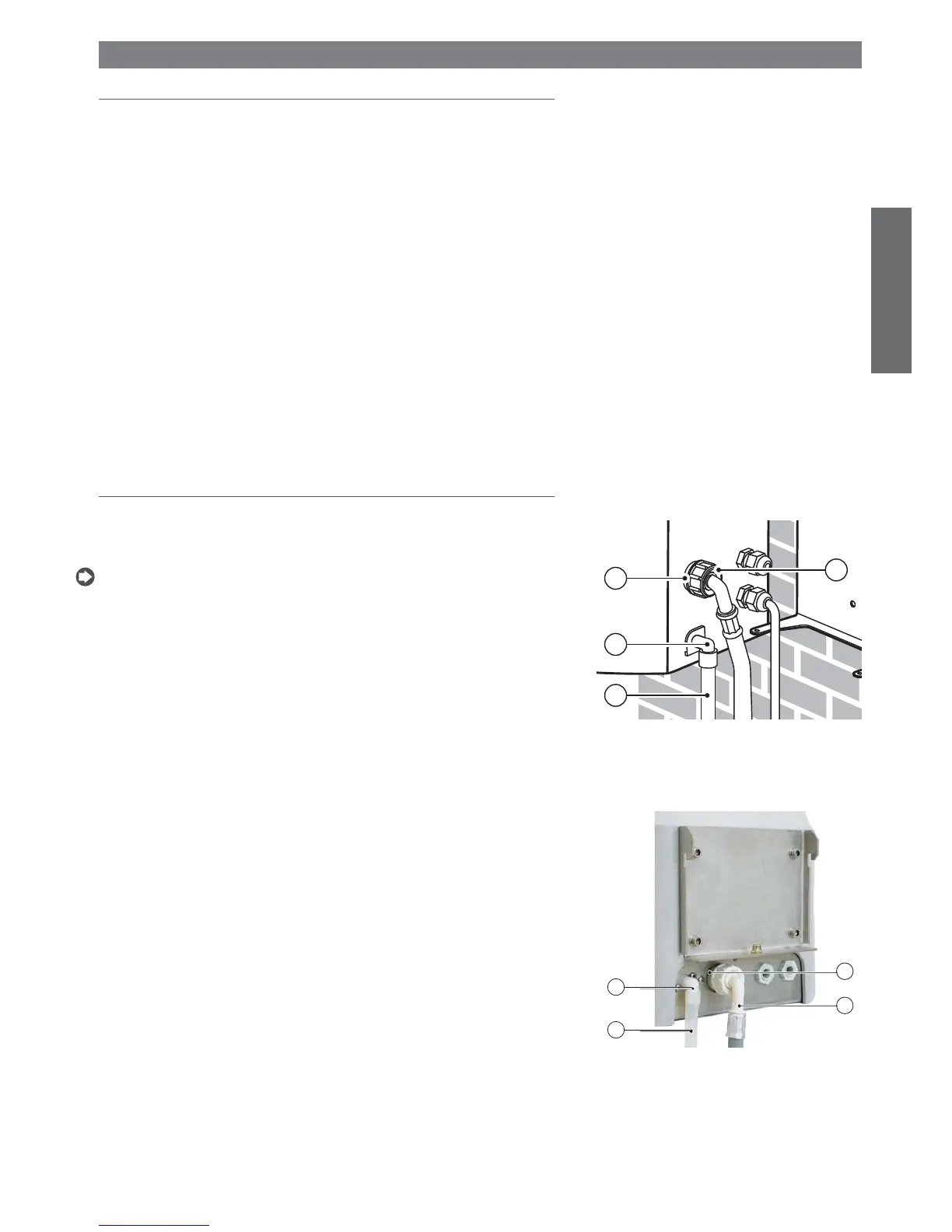
For the humiDisk
65
all the connections, both electrical and water, are also located at the rear, as shown in
Fig 2.b. The operations listed below should be completed before starting actual installation. With reference
to Fig. 2.b:
• connect the water drain hose A, supplied, to the drain elbow B;
• connect end C with the elbow of the water supply hose, supplied, to the fi ll solenoid valve D.
The above-mentioned operations can in any case also be carried out with the unit installed.
1. INSTALLATION
Fig. 2.a
Fig. 2.b

 Loading...


