E N G L I S H
µC
2
- +030220731 - rel. 1.2 - 26.10.2007
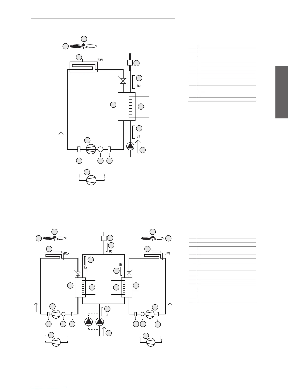
3.3 AIR/WATER chiller
3.3.1 Single circuit
Fig. 3.c.a
3.3.2 two circuits, 2 condenser fan circuits and 2 evaporators
Fig. 3.c.b
Key:
1 condernser fan overload
2 fan
3 condenser probe
4 flow switch
5 outlet evaporator probe
6 fan
7 antifreeze heater
8 inlet evaporator probe
9 compressor 1
10 high pressure
11 compressor overload
12 low pressure
13
water pump
14 compressor 2
Key:
1 condenser fan overload 1 and 2
2 fan 1 and 2
3 condenser probe 1 and 2
4 flow switch
5 outlet temperature probe
6 evaporator 1 and 2
7 outlet evaporator probe 1 and 2
8 antefreeze heater 1 and 2
9 compressor 1
10 high pressure 1 and 2
11 compressor overload 1 and 2
12 low pressure 1and 2
13
inlet evaporator probe
14 compressor 2
15 water pump
16 compressor 3
17 compressor 4

 Loading...


