E N G L I S H
µC
2
- +030220731 - rel. 1.2 - 26.10.2007
7. CONNECTIONS,ACCESSORIES AND OPTIONS
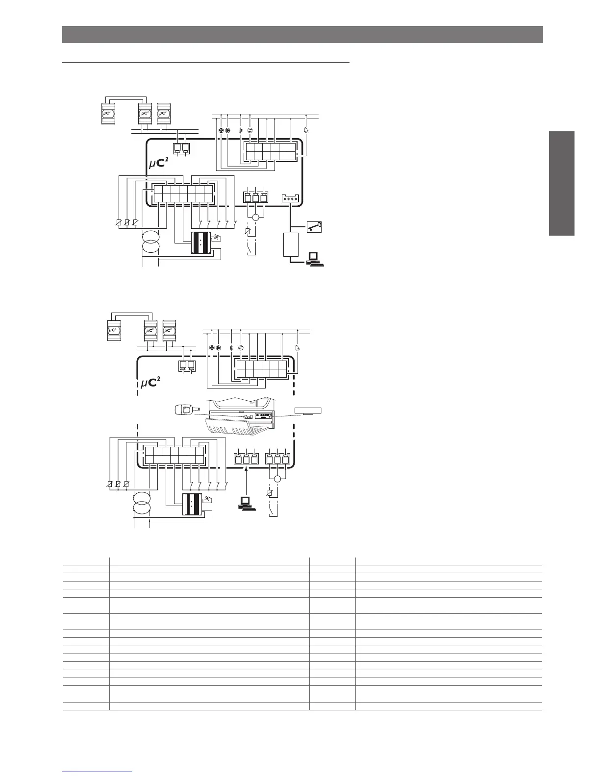
7.1 Connection diagram
The following figure shows the connection diagram for the µC2, in the panel and DIN rail versions.
Panel version
Fig. 7.a
DIN rail version
Fig. 7.b
I/O layout
µC
2
Description Expansion Description
B1 Control probe (Evaporator inlet/ambient) B5 Output probe in common with 2 evaporators (only with 2 circuits)
B2 Protection probe (evaporator outlet/outlet) B6 Circuit 2 protection probe (2
nd
evaporator output)
B3 Condenser/outside temperature probe
B7 2
nd
condenser temperature probe
B4 (universal) Condenser pressure probe B8 (universal) 2
nd
condenser pressure probe
ID1* Flow switch – thermal overload circuit 1 – cooling/heating – end defrost circuit
1 – step 1 condensing unit – second set point
ID6** Flow switch – thermal overload circuit 2 – end defrost circuit 2 – step 4
condensing unit – second set point
ID2* Flow switch – thermal overload 1 circuit – cooling/heating – end defrost circuit
1 – step 2 condensing unit – second set point
ID7** Flow switch – thermal overload circuit 2 – end defrost circuit 2 – step 4
condensing unit– second set point
ID3 High pressure circuit 1
ID8 High pressure circuit 2
ID4 Low pressure circuit 1 ID9 Low pressure circuit 2
ID5 Remote ON/OFF – reverse cycle condensing unit if reversible ID10
Y1 Ramp circuit 1 (condenser) Y2 Ramp circuit 2 (condenser)
C1/2-NO1 Compressor 1 C6/7-NO6 Compressor 3 (1 in 2nd circuit)
C1/2-NO2 Heater or reversing valve in 1st circuit C6/7-NO7 Heater or reversing valve in 2nd circuit
C3/4-NO3 Fan 1/evaporator pump
C8/9-NO8 Fan 2/condenser pump/backup
C3/4-NO4
Compressor 2 (capacity-control compressor 1) C8/9-NO9 Compressor 4 (capacity-control compressor 2) or reversing valve circuit 1
or reversing valve circuit 2
C5-NO5 Alarm or reversing valve C10-NO10 Warning or reversing valve circuit 2
Table 7.a
*= Any of the options for P08 can be selected (see Table 5.11)
**= Any of the options for P08 can be selected, except for E/I and E/I delay.

 Loading...


