31
E N G L I S H
µC
2
- +030220731 - rel. 1.2 - 26.10.2007
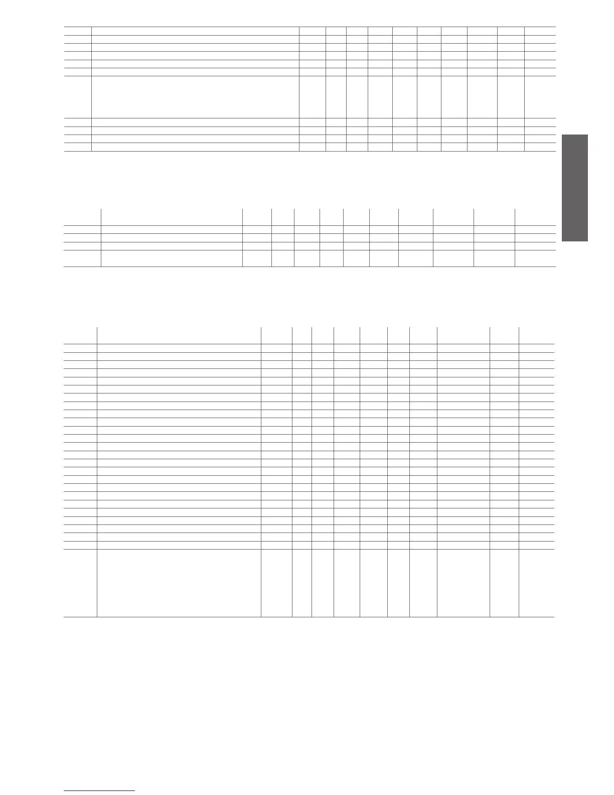
r17 Cooling compensation constant U -5.0 +5.0 - 0.1 0.0 - 51 (R/W) 51 Analog
r18 Maximum distance from the set point U 0.3 20.0 °C/°F 0.1 0.3 - 52 (R/W) 52 Analog
r19 Start compensation temperature in cooling mode U -40 176.0 °C/°F 0.1 30.0 - 53 (R/W) 53 Analog
r20 Start compensation temperature in heating mode U -40 176.0 °C/°F 0.1 0 - 54 (R/W) 54 Analog
r21 Second cooling set point from external contact D r13 r14 °C/°F 0.1 12.0 - 55 (R/W) 55 Analog
r22 Second heating set point from external contact D r15 r16 °C/°F 0.1 40.0 - 56 (R/W) 56 Analog
r27 Enable accumulation vessel suppression
0= Disabled
1= Enabled in cool
2= Enabled in Heat
3= Always enabled
F 0 3 flag 1 0 - 88 (R/W) 216 Integer
r28 Minimum time to determine low load conditions F 0 999 s 1 60 - 89 (R/W) 217 Integer
r29 Low load differential in chiller mode F 0.3 50.0 °C/°F 0.1 3.0 - 58 (R/W) 58 Analog
r30
Low load differential in heat pump mode F 0.3 50.0 °C/°F 0.1 3.0 - 59 (R/W) 59 Analog
r31
Heating compensation constant U -5.0 +5.0 - 0.1 0.0 - 60 (R/W) 60 Analog
Table 4.i
4.3.10 Firmware parameters (F-r*)
display
indicat.
parameter and description default
level
min. max. U.O.M. variat. def. visibility supervis.
variable
Modbus variabile type
H96 Software version Driver 2 D 0 999 flag XV 4 (R) 132 Integer
H97 Software version Driver 1 D 0 999 flag V 3 (R) 131 Integer
H98 Expansion software version D 0 999 flag X 2 (R) 130 Integer
H99 Software version (to be displayed after instrument
start-up)
D 0 999 flag - 1 (R) 129 Integer
Table 4.j
4.3.11 Supervisor only variables
display
indicat.
parameter and description default
level
min. max. U.O.M. variat. def. visibility supervis. variable Modbus variabile
type
- Digital input 1 - 0 1 Flag 1 - - 43 (R) 43 Digital
- Digital input 2 - 0 1 Flag 1 - - 44 (R) 44 Digital
- Digital input 3 - 0 1 Flag 1 - - 45 (R) 45 Digital
- Digital input 4 - 0 1 Flag 1 - - 46 (R) 46 Digital
- Digital input 5 - 0 1 Flag 1 - - 47 (R) 47 Digital
- probe B4 digital input - 0 1 Flag 1 - - 48 (R) 48 Digital
- Digital output 1 - 0 1 Flag 1 - - 49 (R/W) 49 Digital
- Digital output 2 - 0 1 Flag 1 - - 50 (R/W) 50 Digital
- Digital output 3 - 0 1 Flag 1 - - 51 (R/W) 51 Digital
- Digital output 4 - 0 1 Flag 1 - - 52 (R/W) 52 Digital
- Digital output 5 - 0 1 Flag 1 - - 53 (R/W) 53 Digital
- Unit status, 1= ON or 0= standby - 0 1 Flag 1 0 - 54 (R/W) 54 Digital
- 1= Cooling or 0= Heating - 0 1 Flag 1 1 - 55 (R/W) 55 Digital
- Digital input 6, 2nd circuit - 0 1 Flag 1 - - 56 (R) 56 Digital
- Digital input 7, 2nd circuit - 0 1 Flag 1 - - 57 (R) 57 Digital
- Digital input 8, 2nd circuit - 0 1 Flag 1 - - 58 (R) 58 Digital
- Digital input 9, 2nd circuit - 0 1 Flag 1 - - 59 (R) 59 Digital
- Digital input 10, 2nd circuit - 0 1 Flag 1 - - 60 (R) 60 Digital
- Probe B8 digital inputs, 2nd circuit - 0 1 Flag 1 - - 61 (R) 61 Digital
- Digital output 6 - 0 1 Flag 1 - - 62 (R/W) 62 Digital
- Digital output 7 - 0 1 Flag 1 - - 63 (R/W) 63 Digital
- Digital output 8 - 0 1 Flag 1 - - 64 (R/W) 64 Digital
- Digital output 9 - 0 1 Flag 1 - - 65 (R/W) 65 Digital
- Digital output 10 - 0 1 Flag 1 - - 66 (R/W) 66 Digital
- Enable digital output from Supervisor - 0 8000 Flag 1 - - 13 (R) Integer
Defrost status
0= no Defrost
1= Def. circuit 1
2= Def. circuit 2
3= Def. circuit 1 and 2
5= Fan Def. circuit 1
10= Fan Def. circuit 2
15= Fan Def. circuit 1 and 2
- - - - - - 104 (R) stato defrost Integer
Table 4.l

 Loading...


