42
E N G L I S H
µC
2
- +030220731 - rel. 1.2 - 26.10.2007
- µC
2
network configuration
H08: Establishes the layout of the tLan network.
0= µC
2
only
1= µC
2
+ valve
2= µC
2
+ exp.
3= µC
2
+ exp. + valve
- Enable keypad
H09:
Used to disable the modification of the DIRECT and USER parameters from the keypad. The
value of the parameters can always be displayed. The enable/disable cooling, heating and reset counter
functions are also available.
Values:
0: keypad disabled
1: keypad enabled (default)
- Serial address
H10: Establishes the address of the instrument for the serial connection, via an optional board, to a PC
for supervision and/or telemaintenance.
- Selection map outputs
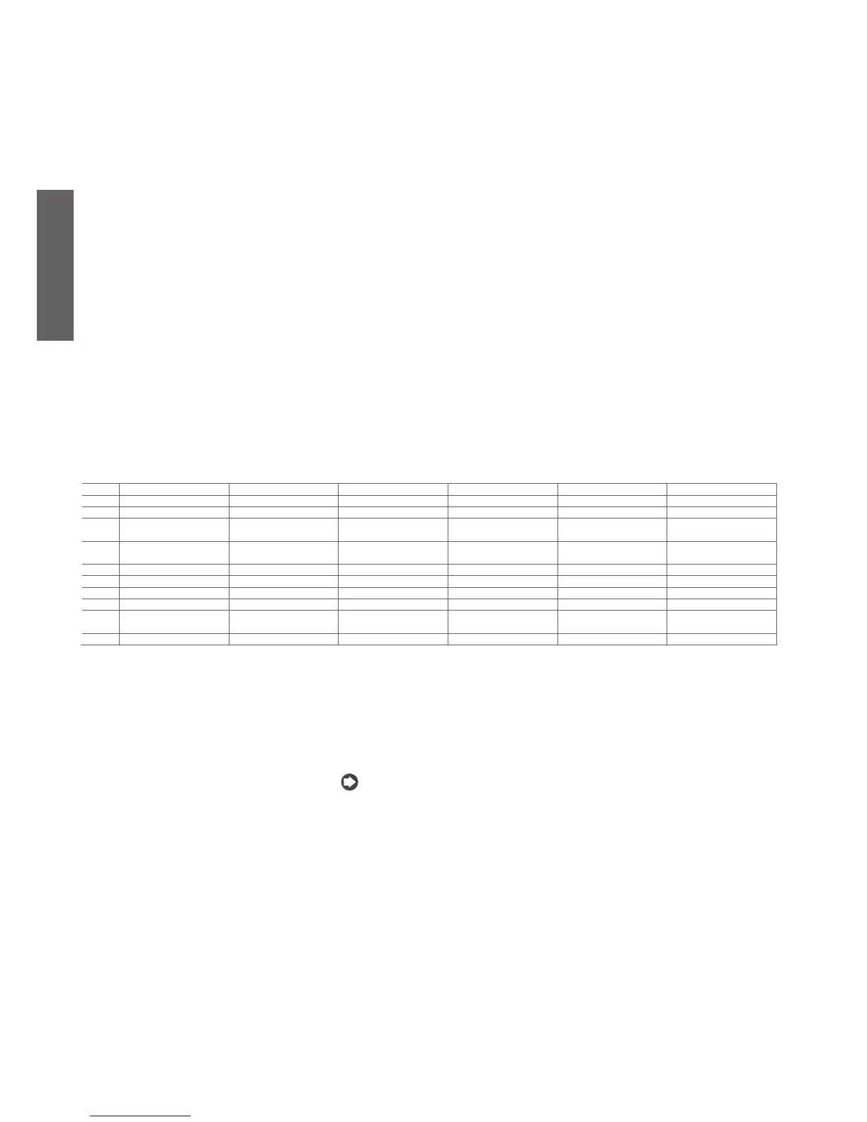
H11: This parameter is used to arbitrarily associate some digital outputs to the devices on the unit.
H11= 0: standard (default); for units with one compressor per circuit (H04=0, 2).
H11= 1: For cooling only units with two compressors (H01=0, 2, 4, 7, 9 and H04=1, 3, 5)
H11= 2: The outputs of the expansion follow the same logic for the 2nd circuit. For H01= 1, 3, 5, 6, 8, 10 and H04=
1, 3, 5
H11= 3: The outputs of the expansion follow the same logic for the 2nd circuit. For H01= 1, 3, 5, 6, 8, 10 and H04=
1, 3, 5
H11= 4: For H01= 1, 3, 5, 6, 8, 10 and H04= 0, 1
H11= 5: For cooling only units with two compressors (H01= 0, 2, 4, 7, 9, and H04= 0)
associazione agli organi dell’unità
uscite
H11=0 H11= 1 H11= 2 H11= 3 H11= 4 H11= 5
C1
compressor 1 compressor 1 compressor 1 compressor 1 compressor 1 compressor 1
C2
heater 1 heater 1 heater 1 reversing valve 1 reversing valve 1 heater 1
C3
Pump/evaporator (fan) (on
air/air units)
Pump/evaporator (fan) (on
air/air units)
Pump/evaporator (fan) (on
air/air units)
Pump/evaporator (fan) (on
air/air units)
evaporator pump Pump/evaporator (fan) (on
air/air units)
C4
reversing valve 1 Compressor 2 (or capacity
control comp. 1)
Compressor 2 (or capacity
control comp. 1)
Compressor 2 (or capacity
control comp. 1)
Compressor 2 (or capacity
control comp. 1)
condenser fan 1
C5
alarm alarm reversing valve 1 alarm alarm alarm
C6
compressor 2 compressor 3 compressor 3 compressor 3 not used compressor 2
C7
heater 2 heater 2 heater 2 reversing valve 2 heater 1 heater 2
C8
Condenser pump/backup Condenser pump/backup Condenser pump/backup Condenser pump/backup Condenser pump/backup Condenser pump/backup
C9
reversing valve 2 Compressor 4 (or capacity
control comp. 2)
Compressor 4 (or capacity
control comp. 2)
Compressor 4 (or capacity
control comp. 2)
not used condenser fan 2
C10
Warning Warning reversing valve 2 Warning Warning Warning
- Capacity-control logic
H12: Specifies the logic for the activation of the capacity-control steps for the compressors and the 4-way
reversing valve.
H12 = 0: 4-way reversing valve and capacity-control normally energised
H12 = 1: 4-way reversing valve and capacity-control normally de-energised. Default value.
H12 = 2: 4-way reversing valve normally de-energised and capacity-control normally energised
H12 = 3: 4-way reversing valve normally energised and capacity-control normally de-energised.
Note: in the event of capacity-control, the rotation between compressor and corresponding valve is disa-
bled. FIFO or time logic can be used between the 2 circuits to optimise the starts or the operating hours
of the 2 compressors (1 per circuit).
- Function of the second pump
H21: This parameter defines how the output dedicated to the second pump must be managed.
H21= 0: the second pump is disabled.
H21= 1: the second pump is used only as a backup.
If the flow switch and corresponding alarm are activated, the pumps are switched over:
if the alarm passes, a warning is shown on the display and the warning relay is activated, while the
unit continues to operate with the Backup pump. When the next alarm is activated the pumps will be
switched over.
if the alarm remains active even with the second pump on for longer than the time set for P1, the
generic alarm is generated and the unit is switched OFF.
H21= 2: the second pump represents a backup pump. The two pumps are never used at the same time
but each 24 hours, are switched over. In the event of flow alarms, the logic is the same as for setting 1.
After being switched over due to the flow alarm, the 24-hour timer is set to zero.
H21= 3: the second pump is used as an ON/OFF device in the same way as the condenser fan (which in
this case is not present), in ON/OFF mode, with the same settings (in fact in this case the pump replaces
the fan, including the symbol).
H21= 4: the second pump is used for the condenser but is always ON. In this case the pump symbol is
•
•

 Loading...


