E N G L I S H
µC
2
- +030220731 - rel. 1.2 - 26.10.2007
Panel installation (code MCH200TP00)
This version has been designed for panel installation, with the drilling template measuring 127 x 69 mm
with 2 circular holes, diameter 4 mm, as shown in Fig. 7.m. For installation proceed as follows (Fig. 7.n.a):
connect the telephone cable;
insert the terminal, without the front frame, in the opening, and use the countersunk screws to fasten
the device to the panel;
finally, apply the click-on frame.
Wall-mounting (code MCH200TW00)
The version of the terminal for wall-mounting requires the rear of the case A to be fastened (Fig. 7.n.b)
using a standard 3-module switch box.
fasten the rear of the case to the box using the round-head screws;
connect the telephone cable;
rest the front panel on the rear of the case and fasten the assembly using the countersunk screws, as
shown in Fig. 7.n.b.;
finally, apply the click-on frame.
Electrical connections (Fig. 7.o.a-7.o.b)
Connect the RS485 serial line leaving the power supply “RJ12 Power supply” to the supervisor input on
the µC
2
, using a twisted pair cable with shield. Power terminals G-G0 from a transformer with a 250 mAT
fuse, as shown in the diagram in Fig. 7.o.a-7.o.b. Make the connection between the power supply “RJ12
Power supply” and the terminal using the telephone cable (code S90CONN002 l = 80 cm) supplied. If
the cable is not long enough, use a pin-to-pin telephone cable with a maximum length of 40 m.
Warnings:
only use safety transformers;
for safety reasons a 250 mA slow-blow fuse must be fitted in series with terminal ‘G’;
if using the same transformer for the µC
2
and the terminal, respect the polarity G-G0 as per the wiring
diagram. Reversing the polarity is the same as short-circuiting the secondary of the transformer;
do not earth the secondary of the transformer.
24 Vac power supply line (G- G0)
Typical length Minimum cross-section
250 m 1,5 mm
2
(AWG16)
100 m 0,5 mm
2
(AWG20)
50 m 0,35 mm
2
(AWG22)
Table7.e
RS485 serial line to µC
2
Speed 19200 baud
Maximum RS485 distance 1 Km (with 120 ohm terminals)
Cable characteristics twisted pair + shield
Cross-section
AWG22
Capacitance per metre < 90 pF/m (for example, BELDEN 8761-8762 cables)
Table7.f
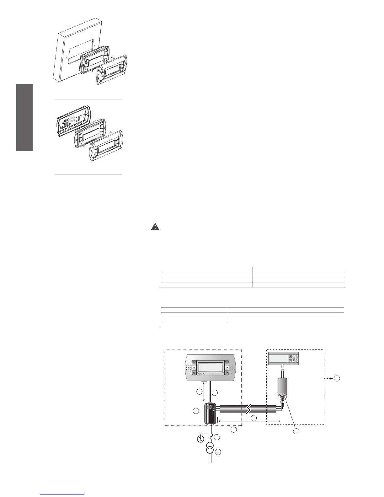
Connection diagram (local power supply)
•
•
•
•
•
•
•
•
•
•
•
Fig. 7.n.a
Fig. 7.n.b
Fig. 7.o.a
Key:
1. alternative: MCH200001*+FCSER0000 (see Fig. 7.o.b);
2. Insert 120 ohm terminal resistor between Tx/Rx+ and Tx/Rx-
for lines longer than 20 m;
3. length max.= 1000 m;
4. RS485 twisted pair + shield Rx/Tx+, Rx/Tx-, GND;
5. fuse 250 mA;
6. 24 Vac 3 VA;
7. telephone cable;
8. length max= 40 m;
9. RJ12 power supply.

 Loading...


