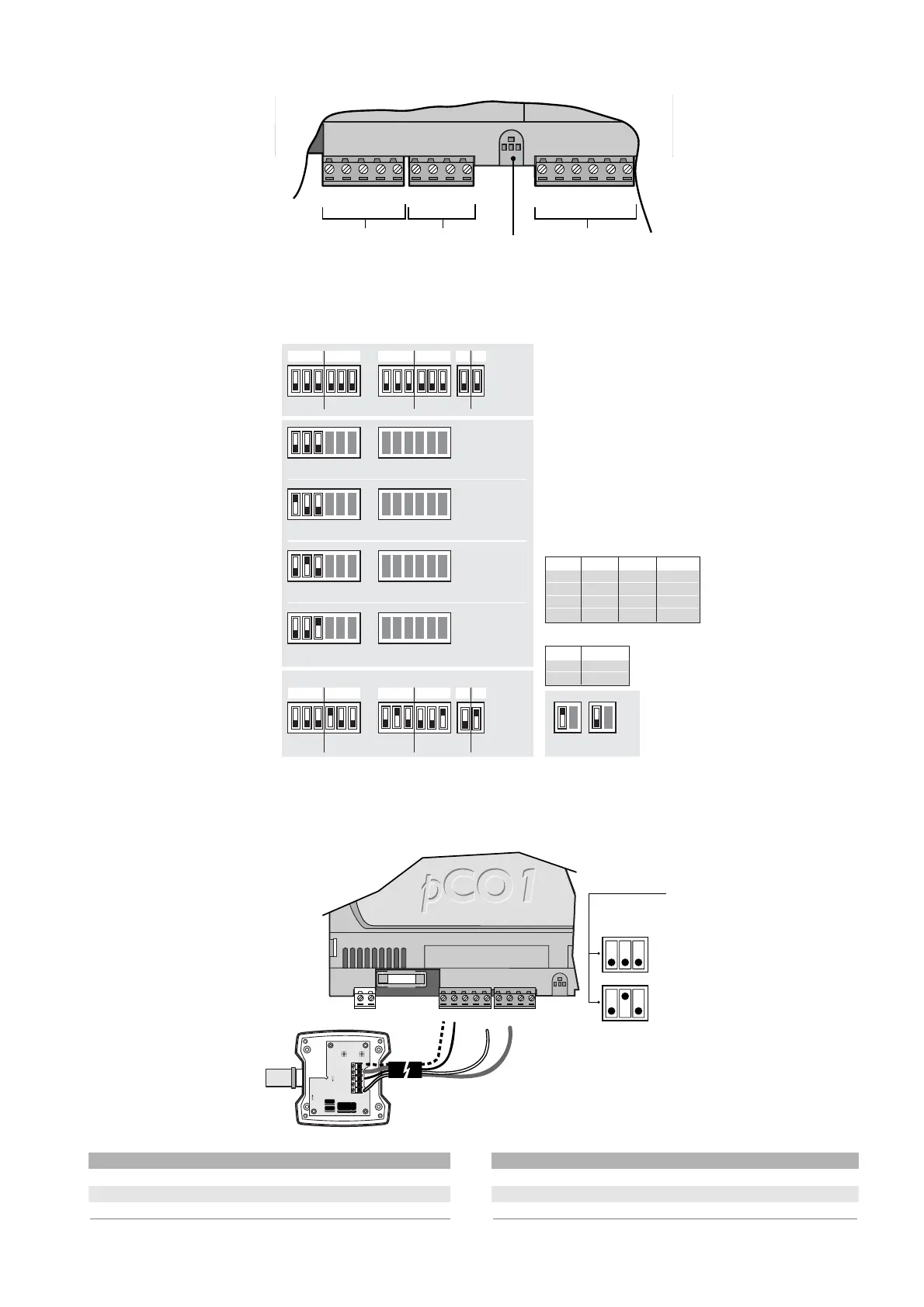
4.4 Collegamento degli ingressi analogici
Gli ingressi analogici sono
configurabili per i più diffusi
sensori presenti sul mercato: NTC,
0/1 V, 0/5 V, 0/20 mA, 4/20 mA.
La selezione hardware tra i diversi
tipi di sensori viene effettuata
tramite i relativi dip-switch, come
nella seguente figura.
AVVERTENZA:
per l’alimentazione delle sonde
attive, è possibile utilizzare i 24 Vdc
disponibili al morsetto +VDC, la corrente massima erogabile
è di 100 mA, protetta termicamente contro i cortocircuiti.
4.4.1 Collegamento sonde attive di temperatura ed umidità
Al pCO
1
possono essere
collegate tutte le sonde attive
di temperatura ed umidità
della serie AS* Carel,
configurate come 0/1 V
oppure come 4/20 mA.
Gli ingressi che possono
accettare questi sensori
sono: B1, B2, B3, B4, previa
configurazione da programma
applicativo e dai dip-switch
relativi sulla scheda.
Di seguito viene illustrato lo
schema di collegamento e la
corretta posizione dei
dip-switch.
morsetti pCO
1
morsetti sonda descrizione
GND M riferimento
+Vdc +(G) alimentazione
B1, B2, B3, B4 out H, ntc ingressi sonde universali
Tab. 4.4.1.1
4.4 Connecting the analogue inputs
The analogue inputs can be
configured for the more common
sensors on the market: NTC, 0/1V,
0/10V, 0/20mA, 4/20mA.
The different types of sensors can
be selected using the
corresponding dipswitches, as in
the following figure.
WARNING: for the power supply to
the active probes, the 24Vdc
available at the +VDC terminal can
be used; the maximum current is 100mA, thermally protected against
short-circuits.
4.4.1 Connecting active temperature and humidity probes
The pCO
1
can be
connected to all the Carel
AS* series active
temperature and humidity
probes configured as 0/1V
or 4/20mA.
The following inputs can
accept these sensors: B1,
B2, B3, B4, after having
configured the program and
the corresponding
dipswitches on the board.
The connection diagram
and the correct position of
the dipswitches are shown
below.
pCO
1
terminal probe terminal description
GND M reference
+Vdc +(G) power supply
B1, B2, B3, B4 out H, NTC universal probe inputs
Table 4.4.1.1
21
pCO
1
manual - cod. +030221840 rel. 1.0 - 09/07/02

 Loading...


